background image

Parts Catalog

SHANGHAI HUIGONG NO.3 SEWING MACHINE FACTORY

GC20688-DC/GC20688-BDC

Compound-Feed, Heavy Material Lockstitch Sewing

Machine With Edge Cutter

Instruction Manual

Summary of Contents for GC20688-BDC

Page 1: ...Parts Catalog SHANGHAI HUIGONG NO 3 SEWING MACHINE FACTORY GC20688 DC GC20688 BDC Compound Feed Heavy Material Lockstitch Sewing Machine With Edge Cutter Instruction Manual...

Page 2: ...Adjusting the lower thread tension 6 7 Installing the needle 6 8 Alternating presser foot movement amount 6 9 Adjusting the presser foot pressure 6 10 Adjusting the stitch length 6 11 Using the manua...

Page 3: ...the vertical cutter is turned off 19 2 Timing of the deactivation of the knife 19 3 Position of the release block 19 4 Lubrication of the eccentric 19 5 Stroke of the knife 19 6 Timing of knife movem...

Page 4: ...e lubricating 3 When a new sewing machine is first turned on verify the rotational direction of the pulley with the power on The pulley should rotate counterclockwise when viewed from the pulley 4 Ver...

Page 5: ...the picture All the pins on the control box have signals of function showing and usually different wires have different kinds of joint Caution the pin of synchronizer wire is the same with another tw...

Page 6: ...Install the operation panel 1 to the set plate 2 with the three screws 3 2 Install the set plate 2 to the back of the machine arm with the two screws 4 4 Adjusting the needle stop position 1 Adjusting...

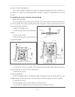
Page 7: ...a Turn off the power switch n a position over the mark on the belt cover the needle down stop position disc 2 s ion of machine pulley rotation When the black mark stops is no need to loosen the screw...

Page 8: ...e the needle th ead tension re and wind the end of the thread clockwise arou n wind ound on remove the b nife 3 5 read is unwound from it moves in the opposite direction to th 6 pass the thread throug...

Page 9: ...ressure should be set as o that the dial eed adjustment dials 2 and 3 can be used to set two diff Installing the needle Note Before attach needle b 1 Turn the b est position 2 Loosen the needle clampi...

Page 10: ...t time only Furthermore if the switch 3 is pressed when neither starting nor end back tacking has been set back tacking is carried out for the first time only 3 Needle up or down switch If the switch...

Page 11: ...n oil Turn on the power switch Depress the treadle gently and check that the oil level rises in the oil sight glass a The wick 1 leading from the oil sump to the oscillating crank 4 must be fixed betw...

Page 12: ...e machine pulley to set the feed dog 1 2 Loosen the screw 3 3 Adjust the feed dog s height 4 Tighten the screw 3 17 Adjusting the needle bar height Set the feed adjustment dials to the minimum settin...

Page 13: ...ley to raise the needle bar from its low position to the point that the needle rises 2mm 6 Turn the rotary hook to align the rotary hook tip with the center of the needle 7 Tighten the screw 1 20 Hook...

Page 14: ...5mm above the top of the needle plate 2 when the needle bar is at its lowest position a Loosen the two screws 3 b Turn the machine pulley to set the needle bar to its lowest position c Turn feed cam...

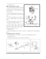
Page 15: ...3 22 Adjusting the opener position Adjust so that the clearance between the needle plate 3 and th when the opener 1 is at its inner rotary hook 2 1 Turn the machine pulley to move the opener 1 in dire...

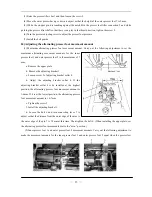
Page 16: ...6mm If it is at the lowest position the alternating presser ghten the screw 5 ver 7 to outer presser foot 2 moveme 5 While the stopper pin 6 is touching against the notch B in the presser foot lifter...

Page 17: ...dle and the top of the feed e needle plate f Move the connecting lever to adjust so that both the inner presser foot 2 and outer presser foot 1 are in contact with the top of the needle plate at this...

Page 18: ...hould be 1 4 1 6 m 1 Loosen the two screws 3 2 Move the thread holding spring 1 to adjust its position and then tighten the screws 3 28 Adjusting the knife timing position After adjusting the position...

Page 19: ...bolt 4 4 Move the driving knife 1 so that the distance between the blade of the fixed knife 2 to the end of the driving knife 1 is 0 5 mm and then tighten the bolt 4 31 Adjusting the driving knife ope...

Page 20: ...ine 4 Turn the thread trimmer cam 2 to adjust the position of e thread trimmer cam 2 so that the center of the pin 1 the enter of the reference hole 3 and the center of the roller 4 of e driving knife...

Page 21: ...e operating lever down Caution Risk of Injury Turn the main switch off Set the vertical cutter only with the sewing machine turned off 2 Stick a pin in drill hole 1 of the outer clutch disc 3 Turn the...

Page 22: ...ion of the oil tube 5 The wick must touch the groove in the eccentric with its knots Tighten screw 6 again 5 Stroke of the knife Loosen screw 9 3 Set the position of the eccentric sleeve 10 in the rad...

Page 23: ...from below the knife carrier 3 to above the knife carrier nif en screw 6 Insert the wrench through the hole in the housing wall Turn shaft 5 When the knife 9 is at the lower dead center the overlap s...

Page 24: ...A ARM BED MECHANISM 21...

Page 25: ...1 1 A17 HF974B8001 Thread tension stud 1 1 A18 H7212I8001 Washer 1 1 A19 H4715B8001 Plug 2 2 A20 HF965B8001 Fixing clamp 1 1 A21 HF964B8001 Winder shaft 1 1 A22 H401030120 Screw 1 1 M3 12 A23 HF952B80...

Page 26: ...rew Slide Plate Slide Plate 2 1 1 2 1 A60 A61 A62 HF986B8001 H401020025 HF982B8001 Spring for slide plate Screw Stopper 2 2 2 2 M2 2 5 1 1 A63 A64 A65 H7331G8001 H4735B8001 HF914B8001 Screw Plug Screw...

Page 27: ...1 M4 6 A90 HF970B8001 Bobbin seat 1 A90 HE41B58001 Bobbin seat 1 A91 HF946B8001 Washer 1 1 A92 HE62B08001 Fixed knife 1 1 8mm A92 HE62B88001 Fixed knife 1 1 3mm A93 HE62B18001 Fixed knife plate 1 1 A...

Page 28: ...B THREAD TENSION REGULATOR MECHANISM 25...

Page 29: ...n release plate 1 1 B19 HF916C8001 Thread guide 1 1 B20 HA310B0705 Tension discs 4 4 B21 HA310B0702 Tension release discs 2 2 B22 HA115B0703 Tension spring 1 B23 HA115B7010 Stopper 2 2 B24 HA310B0701...

Page 30: ...BDC Remarks B44 H415040100 Screw 2 1 B45 HF906C8001 Magnet support 1 1 B46 HF922C8001 Solenoid 1 1 B47 H403050120 Screw 2 2 M5 12 B48 H4710C8001 Tension spring 1 1 B49 H003002040 Nut 1 B50 H003045040...

Page 31: ...C NEEDLE BAR AND THREAD TAKE UP MECHANISM 28...

Page 32: ...00 Retainer ring 1 1 C20 HF932D8001 Ball bearing 1 1 C21 H431060080 Screw 2 2 M6 8 C22 HF929D8001 Bushing 1 1 C23 H431060100 Screw 1 1 M6 10 C24 HF934D8001 Pulley 1 1 C25 H005008080 Washer 1 1 C26 H41...

Page 33: ...1 2 M3 4 C60 HF972G8001 Screw 1 1 C61 JZDP1700P2301Neddle 1 2 DP 17 23 C62 HF931G7101 Needle bar bracket 1 1 C63 H403040100 Screw 1 1 M4 10 C64 HF943G8001 Oil satchel 1 1 C65 HF947G8001 Oil wick 3 3...

Page 34: ...D PRESSER FOOT MECHANISM 31...

Page 35: ...3E7101 Link 1 1 D18 HA104D0652 Plug 1 1 D19 HF942E8001 Inner presser cam 1 1 D20 H428060060 Screw 2 2 M6 6 D21 HF946E8001 Inner presser rod 1 1 D22 HF947E8001 Bearing 1 1 D23 HF948E8001 Rod pin 1 1 D2...

Page 36: ...14B8001 Screw 2 2 D81 HF934F8001 Guide 1 1 D82 HF928F8001 Pin 1 1 D83 HF930F8001 Oil wick 1 1 D84 HF932F8001 Screw 1 1 D85 HF979E8001 Stopper claw 1 1 D86 HF939F8001 Oil wick 1 1 D87 H431050100 Screw...

Page 37: ...E UPPER FEED LIFTING ROCK SHAFT MECHANISM 34...

Page 38: ...ar lifter shaft 1 1 E18 HF906F8001 Spreader shaft bush L2 1 1 E19 H424050160 Set screw 1 1 E20 H003002050 Nut 1 1 E21 HF997F8001 Stopper 1 1 E22 HE61F88001 Crack 1 1 E23 H415060160 Screw 1 1 M6 16 E24...

Page 39: ...Part No Description GC20688 DC GC20688 BDC Remarks E55 H428060160 Screw 1 1 E57 H415040550 Screw 4 4 E58 H005008040 Spring washer 4 4 E59 H005004040 Washer 4 4 E UPPER FEED LIFTING ROCK SHAFT MECHANI...

Page 40: ...F STITCH REGULATOR MECHANISM 37...

Page 41: ...2 M6 8 F21 HF930H8001 Reverse stitching arm U 1 1 F22 HF934H8001 Pin 1 1 F23 H428060060 Bolt 1 1 M6 6 F24 HF927H8001 Collar 1 1 F25 HF933H8001 Rod 1 1 F26 H007013050 E tpye retaining ring 5 2 2 F27 H...

Page 42: ...100100 Thread pin 1 1 M10 10 F53 H3100D2090 Presser spring 1 1 F54 HF963H8001 Key 1 1 F55 HF966H8001 Oil seal 1 1 F56 HF958H8001 Shaft 1 1 F57 HF967H8001 Oil seal 1 1 F58 HF961H8001 Guide 2 2 F59 H005...

Page 43: ...G FEEDING AND FEED LIFTING HOOK SHAFT MECHANISM 40...

Page 44: ...948I8001 Bolt 2 2 G20 HF951I8001 Screw 2 2 G21 HE60I68001 Feed dog 1 1 8mm G21 HE61I18001 Feed dog 1 1 3mm G22 HF949I8001 Feed bracket 1 1 G23 HF953I8001 Pin 1 1 G24 HF929I8001 Oil seal 3 3 G25 HF924E...

Page 45: ...2 2 M6 5 G61 HF919I7101 Lowe feed connecting rod assy 1 1 G62 HF926I8001 Pin 1 1 G63 H007013050 E tpye retaining ring 5 2 2 G64 HF961H8001 Slide block 2 2 G65 HF925I8001 Back sylinder connection 1 1...

Page 46: ...H HOOK SADDLE MECHANISM 43...

Page 47: ...aft mandril 1 1 H19 H415030060 Bolt 2 2 M3 6 H20 H005004030 Washer 2 2 H21 HF914J8001 Driving knife 1 H21 HE40J88001 Driving knife 1 H22 HF913J8001 Driving knife shaft 1 1 H23 H415050250 Bolt 2 2 M5 2...

Page 48: ...1 1 H57 H58 HF989J8001 HF991J8001 Uncork washer Hook support Oil wick 5 5 1 1 H59 H60 H61 HF90AJ8001 HF999J8001 HF90BJ8001 1 1 1 1 1 1 Adjusting pin Adjusting guide rail H62 H63 HF997J8001 HF995J8001...

Page 49: ...965J8001 Screw 3 3 H85 HF966J8001 Bolt 3 3 H86 HF970J8001 Washer 1 1 H87 HF969J8001 Driving gear 1 1 H88 H403030080 Screw 4 4 H89 HC01387018 O ring 1 1 H90 H415040100 Bolt 4 4 M4 10 H91 HG025J8001 Thr...

Page 50: ...I OIL LUBRICATION MECHANISM 47...

Page 51: ...19K8001 Spring 1 1 I20 HF962K8001 Tape 1 1 I21 HA04042160 Screw 2 2 I22 HF960K8001 Guard plate 1 1 I23 HF956K7101 Valve 1 1 I24 HF955K8001 Main oil pipe 1 1 3 5 110 I25 HF920K8001 Oil joint 2 2 I26 HF...

Page 52: ...K48001 Oil pipe 1 1 7 5 100 I47 HE60K58001 Oil pipe 1 1 7 5 110 I48 HF926K8001 Support spring 2 2 I49 HF932K8001 Felt part 1 1 I50 HA300I2040 Cable tie 1 1 I51 HF934K8001 Oil pipe 1 1 3 5 250 I52 HF93...

Page 53: ...J ACCESSORIES 50...

Page 54: ...e 1 1 J13 16250 Nail 10 10 J14 HB01001025 Hexagonal wrench 2 5 1 1 J15 HB01001015 Hexagonal wrench 1 5 1 1 J16 HA300J2070 Screw driver L 1 1 J17 HA300J2200 Screw driver M 1 1 J18 HA300J2210 Screw driv...

Page 55: ...K PNEUMATIC CONTROL MECHANISM 52...

Page 56: ...trol box wire assy 1 1 CN1 K09 H801045200 screw 2 2 K10 HA300J2230 washer 4 4 K11 HE60M47101 pneumatic assy 1 1 K12 HA300I2040 nylon fixer 1 1 K13 HF958M8001 windpipe 2 2 300mm 6 K14 HF914M8001 windpi...

Page 57: ...L KNIFFE MECHANISM 54...

Page 58: ...0160 screw 1 1 M5 16 L18 HE61N78001 oil wick 1 1 L19 HE61N88001 supporting block 1 1 L20 H415040250 screw 1 1 M4 25 L21 H415030140 screw 1 1 M3 14 L22 H005001030 washer 1 1 3 L23 HE61N98001 supporting...

Page 59: ...1 screw link shaft 1 1 1 1 L62 L63 L64 HE66N18001 HE61N08001 HE66N28001 1 1 2 2 1 1 bushing oil nozzle L65 L66 H102050300 HE66N38001 screw collar 1 1 M5 30 1 1 L67 L68 L69 H428040040 H007013070 HE66N4...

Page 60: ...er 1 1 L89 HE68N58001 bushing 1 1 L90 HE68N68001 link 1 1 L91 H415050100 screw 1 1 L92 HE68N88001 pin 1 1 L93 HE68N98001 block 1 1 L94 HE69N08001 control lever 1 1 L95 HF01080300 hand knob 1 1 M8 30 L...

Page 61: ...ness TEL 86 21 64853303 FAX 86 21 64854304 E mail highlead online sh cn http www highlead com cn The description covered in this manual is subject to change for improvement of the commodity without no...

Reviews: