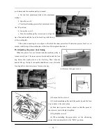
above) Use feed adjustment dial 2 to set the big s
—
7
—
titch length. Use feed adjustment dial 3 to set the little stitch
lengt
he two stitch lengths each time the stitch length change
only while the switch 1 is being pressed.
the switch 3 is pressed when either start back tacking or
ON at the operation panel,
, The needle will move up to the needle up stop position from down stop
(1)
(2)
(3)
13) L
(1)
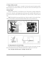
ove oil-filling screw 2 and pour in oil. Check oil l
must be between “EMPTY” and “F
years.
ould be checked and corrected after running-in.
k
itive lubrication
h. The sewing machine will switch between t
switch is pressed.
11) Using the manual switches
(1) Quick reverse switch
Back tacking is carried out during sewing
(2) Auto back tacking select switch
If
end back tacking has been set to
back tacking is canceled for the first time only. Furthermore,
if the switch 3 is pressed when neither starting nor end back
tacking has been set, back tacking is carried out for the first
time only.
(3) Needle up or down switch
If the switch 4 is pressed
position or move down to the needle down stop position from up stop position.
12) Cleaning
The area around the feed dog and the hook should be cleaned ev
Remove any thread scraps from inside the rotary hook.
Keep the control box clean.
ubrication
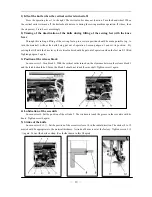
Check the oil level at the sight glass 1 every week. If the oil
enough, rem
ery day.
is not
evel at
ULL”.
sight glass 2. The oil level
Replace oil-filling screw 2. After running for 500 hours since buying
the new sewing machine, the oil must be changed. Then change the oil
every two
(2) The oil quantity is pre-set at a relatively high level in order to ensure
adequate lubrication during running–in. This setting sh
(approx. 50 hours). The hoo
is to have pos
with the least possible
amount of oil. Let the sewing
machine run approx.2
minutes. And run in intervals.
Summary of Contents for GC20688-BDC
Page 24: ...A ARM BED MECHANISM 21...
Page 28: ...B THREAD TENSION REGULATOR MECHANISM 25...
Page 31: ...C NEEDLE BAR AND THREAD TAKE UP MECHANISM 28...
Page 34: ...D PRESSER FOOT MECHANISM 31...
Page 37: ...E UPPER FEED LIFTING ROCK SHAFT MECHANISM 34...
Page 40: ...F STITCH REGULATOR MECHANISM 37...
Page 43: ...G FEEDING AND FEED LIFTING HOOK SHAFT MECHANISM 40...
Page 46: ...H HOOK SADDLE MECHANISM 43...
Page 50: ...I OIL LUBRICATION MECHANISM 47...
Page 53: ...J ACCESSORIES 50...
Page 55: ...K PNEUMATIC CONTROL MECHANISM 52...
Page 57: ...L KNIFFE MECHANISM 54...


