are lo
ned.
um
ey toward you to align the
tip o
dog with the top
of th
e tip of the needle should move away from the
feed
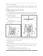
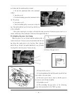
(1) Remove the upper cover 4.
(2) Loosen the two screws 1.
(3) Turn the machine pulley until the needle tip and the feed
dog’s up face is the same plane.
e point of
ternating
wered and the machine pulley is tur
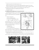
a. Set the feed adjustment dials to the maxim
settings.
b. Open the cover 4
c. Turn the alternating presser foot movement dial to
the “B” position.
d. Loosen the screw 3
e. Turn the machine pull
f the needle and the top of the feed
e needle plate.
f. Move the connecting lever to adjust so that both the inner presser foot 2 and outer presser foot 1 are in
contact with the top of the needle plate at this time. Then tighten the screw 3.
25)
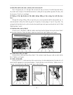
Adjusting the presser foot timing
When the presser feet are lowered and the machine pulley is
turned toward you. The inner presser foot should touch the feed
dog before the needle arrives at the feed dog. Then when the
needle lifts up, th
dog before the inner presser foot moves away.
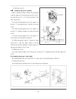
(4) Turn inner presser cam to adjust so that th
inner presser cam is facing straight up.
(5) Tighten the screws 2.
(6) When installing the upper plate, set the al
presser foot movement dial to the “MIN.” position.
—
14
—
Summary of Contents for GC20688-BDC
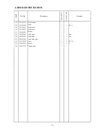
Page 24: ...A ARM BED MECHANISM 21...
Page 28: ...B THREAD TENSION REGULATOR MECHANISM 25...
Page 31: ...C NEEDLE BAR AND THREAD TAKE UP MECHANISM 28...
Page 34: ...D PRESSER FOOT MECHANISM 31...
Page 37: ...E UPPER FEED LIFTING ROCK SHAFT MECHANISM 34...
Page 40: ...F STITCH REGULATOR MECHANISM 37...
Page 43: ...G FEEDING AND FEED LIFTING HOOK SHAFT MECHANISM 40...
Page 46: ...H HOOK SADDLE MECHANISM 43...
Page 50: ...I OIL LUBRICATION MECHANISM 47...
Page 53: ...J ACCESSORIES 50...
Page 55: ...K PNEUMATIC CONTROL MECHANISM 52...
Page 57: ...L KNIFFE MECHANISM 54...

