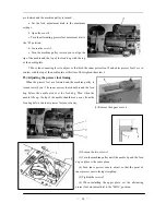
2) Oil pan
(1) Install the oil pan 3 to the underside of the worktable 1 in the place shown in the illustration using the
nails 2.
(2) From front view, the oil pan 3 to the side is 60mm; from right view, the oil pan 3 to the side is 80mm.
3) Operation panel
—
3
—
(1) Install the operation panel 1 to the set
plate 2 with the three screws 3.
(2) Install the set plate 2 to the back of the
machine arm with the two screws 4.
4) Adjusting the needle stop position
(1) Adjusting the needle up stop position
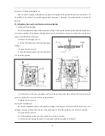
When the sewing machine stops in the
needle up stop position (the stop position of trimming) and the treadle is pressed back, the red mark on the
pulley should be consistent with the mark on the belt cover A. Adjust as follows:
Summary of Contents for GC20688-BDC
Page 24: ...A ARM BED MECHANISM 21...
Page 28: ...B THREAD TENSION REGULATOR MECHANISM 25...
Page 31: ...C NEEDLE BAR AND THREAD TAKE UP MECHANISM 28...
Page 34: ...D PRESSER FOOT MECHANISM 31...
Page 37: ...E UPPER FEED LIFTING ROCK SHAFT MECHANISM 34...
Page 40: ...F STITCH REGULATOR MECHANISM 37...
Page 43: ...G FEEDING AND FEED LIFTING HOOK SHAFT MECHANISM 40...
Page 46: ...H HOOK SADDLE MECHANISM 43...
Page 50: ...I OIL LUBRICATION MECHANISM 47...
Page 53: ...J ACCESSORIES 50...
Page 55: ...K PNEUMATIC CONTROL MECHANISM 52...
Page 57: ...L KNIFFE MECHANISM 54...


