6)
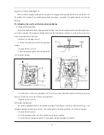
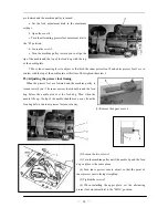
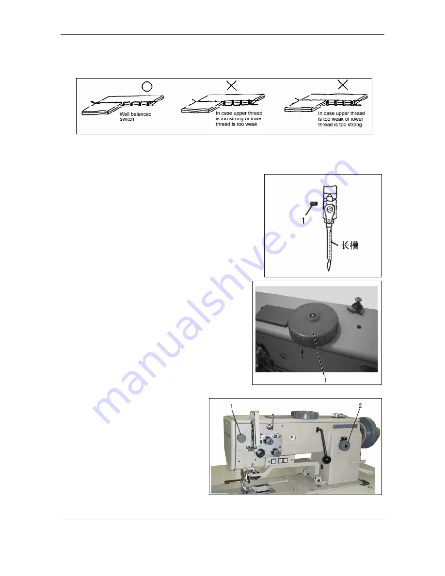
he lower-thread tension should be set in accordance with the type of seam required. Adjust the tension
with screw 7. (See the picture of above)
Adjusting the lower-thread tension
T
—
6
—
7)
e sure to turn off the power.
alance wheel by hand to raise the needle bar to its
high
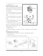
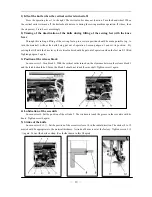
3) Hold the needles so that the two needles side with the long
grooved (faces each other), and insert it as deeply as it will go into
the needle clamping holes( model GC20688-2-D);Hold the needle
to its side with the long groove side(left),then insert the needle as
deeply as it will go into the needle clamping hole(model
GC20688-1-D).
screw.
8)
presser foot can be adjusted within the range
movement dial 1.
foot pressure should be set as
o that the
dial
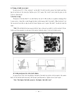
eed adjustment dials 2 and 3 can be used to set two diff
Installing the needle
Note: Before attach needle, b
1) Turn the b
est position;
2) Loosen the needle clamping screw
;
4) Tighten the needle clamping
Alternating presser foot movement amount
The alternating movement amount for the inner presser
foot and the outer
of 1-7 mm using the alternating presser foot
Turn the alternating presser foot movement dial 1 clockwise or
counterclockwise to align the mark. (MIN. A, B, C, D, E, F
MAX. )
9)
Adjusting the presser foot pressure
The presser
weak as possible, but strong enough s
material does not slip. If the presser-adjusting
1 is turned clockwise, the presser foot
pressure will become stronger, and if it is turned
counterclockwise, the pressure will become
weaker.
10)
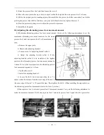
Adjusting the stitch length
The f
erent types of stitch length. (See the picture of
Summary of Contents for GC20688-BDC
Page 24: ...A ARM BED MECHANISM 21...
Page 28: ...B THREAD TENSION REGULATOR MECHANISM 25...
Page 31: ...C NEEDLE BAR AND THREAD TAKE UP MECHANISM 28...
Page 34: ...D PRESSER FOOT MECHANISM 31...
Page 37: ...E UPPER FEED LIFTING ROCK SHAFT MECHANISM 34...
Page 40: ...F STITCH REGULATOR MECHANISM 37...
Page 43: ...G FEEDING AND FEED LIFTING HOOK SHAFT MECHANISM 40...
Page 46: ...H HOOK SADDLE MECHANISM 43...
Page 50: ...I OIL LUBRICATION MECHANISM 47...
Page 53: ...J ACCESSORIES 50...
Page 55: ...K PNEUMATIC CONTROL MECHANISM 52...
Page 57: ...L KNIFFE MECHANISM 54...


