background image

Summary of Contents for GC22618

Page 1: ...Purchasing Dept Copy HIGHLEAD GC22618 CYLINDER BED UNISON FEED SEWING MACHINE Instruction Manual Parts Catalog SHANGHAI HUIGONG N0 3 SEWING MACHINE FACTORY...

Page 2: ......

Page 3: ...TING PRESSER FOOT 6 13 RE SET THE SAFETY CLUTCH MECHANISM 7 14 ADJUSTING THE HEIGHT OF THE FEED DOG 7 15 RELATIVE POSITION OF THE FEED DOG TO NEEDLE PLATE 7 16 ADJUSTING THE HEIGHT OF THE NEEDLE BAR 8...

Page 4: ...tarting operation 1 Ifthe machine s oil pan has an oil sump never operate the machine before filling it 2 If the machine is lubricated by a drop oiled consider revising never operate the machine befor...

Page 5: ...er long distance transportation with jolt A thorough examination must be perfo1med after cleaning the machine Turn the balance wheel to see if there is running obstruction parts collision uneven resis...

Page 6: ...eedle forward the left 3 Tighten the screw Needle bar Long groove facing to the left 5 WINDING THE LOWER THREAD Fig 6 1 Push a bobbin on the bobbin winder spindle 3 as far as it will go Needle screw N...

Page 7: ...ase or to decrease the amount of thread wound on the bobbin 3 Winding strength Strength of the winding can be adjusted with the nut 7 7 REMOVING AND INSERTING THE BOBBIN Fig 7 1 Take out the bobbin Op...

Page 8: ...djust tension turn serrated nut on tension device to the right to increase tension and to the left ifyou desire to decrease it Well balanced stitch Upper thread is too strong or lower thread is too we...

Page 9: ...LENGTH REVERSING LEVER Fig 13 Adjusting the stitch adjustment bar can set stitch length For desired stitch length push the stitch adjustment bar downward 12 ADJUSTING THE LIFT OF THE ALTERNATING PRES...

Page 10: ...anismre engages Fig 15 14 ADJUSTING THE HEIGHT OF THE FEED DOG Fig 16 The max Height ofthe feed dog from the surface to the needle plate is normally 1nnn To adjust this height 1 Set the stitch length...

Page 11: ...r lower the needle bar as may be required Then tighten the screw 22 3nun Fig 17 r c 1 Fig 18 17 ADJUSTING THE HEIGHT OF THE PRESSER FOOT Fig 19 1 Adjustment by the presser bar lifter Loosen the screw...

Page 12: ...qual loosen the two screws 4 and adjust the rotating position ofthe cam faster or slower as may be desired and tighten the screws 19 ADJUSTING THE THREAD TAKE UP SPRING Fig 20 Normally the thread take...

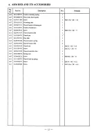
Page 13: ...A ARM BED AND ITS ACCESSORIES 20 19 18 6 17 15 14 10 3 2 63 62 61 26 27 28 29 30 31 32 33 34 35 36 38 39 40 r 41 4 2 43 4 4 i 45 46 1 47 60 59 58 57 10...

Page 14: ...0 Oil guard 1 A19 H3100B2060 Thread take up guard 1 A20 HA300B2160 Screw 1 SMll 64 40 XlQ A21 H4100B2110 Screw 6 SMl 4 24 x9 8 A22 H4100B2100 Hinge 1 A23 HA300B2170 Arm side cover screw 4 A24 H4100B21...

Page 15: ...50 H2504C0013 Screw 1 SMll 64 C32 x7 A51 H2504C0657 Thread tension disk 1 A52 HA310B0701 Thumb nut 1 A53 HA115B7010 Stop disk 1 A54 HA607B0068 Thread tension spring 1 A55 H2504C0656 Thread tension dis...

Page 16: ...B TAKE UP THREAD AND ARM SHAFT MECHANISM 36 35 31 30 29 28 27 26 25 24 23 13 22 14 15...

Page 17: ...rew 2 SM15 64 28 X8 5 B16 HA110D0672 Screw 2 SM15 64 28 x12 B17 H4100C2040 Balance wheel 1 B18 H3205J0661 Ann shaft bushing right 1 B19 H3205C0661 Spring washer 2 B20 HA113F0684 Screw 1 SM15 64 28 x8...

Page 18: ...C ROTATING HOOK SHAFT MECHANISM 14 13 11 7 6 5 4 3 21 15 57 56 39 55...

Page 19: ...1611Dl16 Rotating hook bracket 1 Cl9 H41611D316 Felt 1 C20 H41611D216 Felt 1 C21 H410269Dl6 Guide plate 1 C22 H410270Dl6 Guide plate pin 1 C23 H41622D216 Guide plate slide block 1 C24 H4100D2180 Screw...

Page 20: ...x4 5 C47 H3205C0661 Spring washer 1 C48 H007013025 E type ring 1 GB f896 2 5 C49 H4716D8001 Spring for pulley 1 C50 H4718D8001 Pin 1 C51 H4714D8001 Pin 1 C52 H4717D8001 Lever for pulley 1 C53 H4719D8...

Page 21: ...D FEEDING AND FEED LIFTING MECHANISM 8 11 7 3 2 23 19 28 27 26 25 24 18 12 13 16 20 21...

Page 22: ...c wheel 1 Dll H20111C106 Felt clip 1 D12 H41611E213 Felt 1 Dl3 H41552E212 Oil wick 1 D14 H4112E0696 Pin 1 Dl5 H41552E112 Crank rock for feed lifting 1 Dl6 H4112E0693 Screw 1 SM7 32 32 xt2 5 D17 H4112E...

Page 23: ...E STITCH REGULATOR MECHANISM 2 3 4 17 16 15 14 13 12 11 10 9 8 20...

Page 24: ...40 x6 E07 H4104F0653 Felt 1 E08 H3205G1114 Screw 2 M5x5 E09 H4108F0671 Reverse feed lever 1 E10 H4108F0675 Spring for feed regulator shaft 1 Ell HE00001032 Steel ball 1 GB f308 3 17 E12 H4108F0674 Fee...

Page 25: ...F NEEDLE BAR FEEDING MECHANISM 2 8 27 26 24 __ 23 22 I I I I I 21 20 19 3 Q t _ 4 5 1 6 7 I I I 8 9 10 11 J I f1oe I I i I I I I I I 12 i _________13 15 18 17 16 14 22...

Page 26: ...l1F0651 Vibrating presser foot 1 F20 HA700F2100 Screw 1 SMll 64 40 x7 F21 H3100F2360 Screw 2 SM9 64 40 x7 F22 H3100F2340 guide for slide block 1 F23 H3100F2350 Screw 1 F24 H3100F2070 Vibrating presser...

Page 27: ...ING MECHANISM Fig Part No Description Pcs Remarks No F44 HA106D0662 Screw 2 SMl 4 40 x4 F45 H3100F2370 Stop ring 1 F46 HA7311C306 Screw 2 SM9 64 40 x7 F47 H3100F2180 Needle bearing 1 DCL1710 F48 HA100...

Page 28: ...G PRESSER FOOT MECHANISM 16 17 18 I I I 1 4 I 13 I I 12 I 11 10 25 23 24 25 26 27 28 29...

Page 29: ...sition guide bracket 1 014 H2404I0034 Screw 1 SM9 64 40 x8 5 015 H3100G2020 Presser bar position guide 1 016 HA3411D308 Screw 1 SM15 64 28 x7 017 HA100C2020 Screw 1 SM15 64 28 xlQ 018 H3104B0654 Press...

Page 30: ...H ACCESSORIES 17 18 19 J 0 21 16 16 1 00 J 15 14 18 t Q 22 11 1 23 10 9 JJ 27 28 5 29 4 30 3 31 2 32 37 36 27...

Page 31: ...4 GB flOO 4 5x25 H16 H201500065 Knee lifter 2 H17 H201500067 Set blore 1 H18 HA300J2180 Screw 4 SM5 16 18 X16 Hl9 H4100I2010 Knee lifter shaft 1 H20 H201500066 Knee lifter shaft 1 H21 H201500070 Coil...

Page 32: ...Shanghai China Zip Code 201103 Overseas Business TEL 86 21 64853303 FAX 86 21 64854304 E mail highlead online sh cn http www highlead com cn The description covered in this manual is subject to chang...

Reviews: