—
6
—
(
2
)
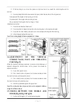
Lean the machine head backward.
(
3
)
Loosen the feed lifting rock shaft crank set screw A and B.
(
4
)
Set the needle at the lowest position.
(
5
)
Adjust the distance between presser bar and vibration bar to 8mm and temporarily tighten the feed
lifting rock shaft crank set screw A and B.
(
6
)
Check the right feed lifting rock shaft crank is connected with the link at right angle,as shown in
Fig.19.
(
7
)
If the connection is not at righr angle,remove the back cover,loosen screw C .
(
8
)
And regulate the right angle.
(
9
)
After the complention of adjustment,fully tighten the screw A,B and C.
Note:At the same time the make sure that the position between the needle and the feed dog.
16.
SAFETY CLUTCH DEVICE(Fig.21,Fig.22)
Safety clutch device is installed to prevent the hook and belt from damage in case the thread is caught into the
hook when the machine is loaded abnormally during operation.
(
1
)
Function of safety clutch
a.When the safety clutch operate,the belt pulley will be unloaded,the lower shaft will stop.Only the arm
shaft operate.The machine stop operation.
b.Clean the thread thoroughly which is caught into the hook.
c.Turn the belt bushing by hand,check the lower shaft rorates lightly.Then set the clutch device in the
starting position.
(
2
)
Set the safety clutch
a.While pressing down the push botton on the bed by left hand,turn the pulley slowly by right hand away
from you as shown in Fig.21.
b.When the belt pulley stopped by the gear plate,then turn the pulley more firmly.
c.Release the push botton,the safety cluth device is set.
(
3
)
Force applied to the safety clutch
a.The force applied to the safety clutch is the smallest when the mark on the eccentric pin faces the center
of the lower shaft.The force proprotinally increases as the mark faces the outside.
b.To adjust the force slide the belt,loosen the set screw,and turn eccentric pin.
c.After the adjustment,make sure to fasten the set screw.
Summary of Contents for GC24698-BLHL
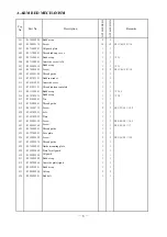
Page 9: ...A ARM BED MECHANISM 7 7 ...
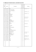
Page 11: ...B THREAD TENSION REGULATOR MECHANISM 9 9 ...
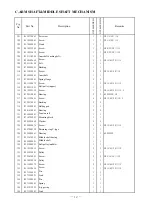
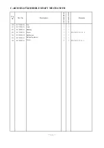
Page 13: ...C ARM SHAFT MIDDLE SHAFT MECHANISM 11 11 ...
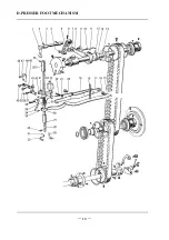
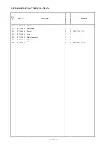
Page 16: ...D PRESSER FOOT MECHANISM 14 14 ...
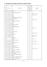
Page 19: ...E NEEDLE BAR THREAD TAKE UP MECHANISM 17 17 ...
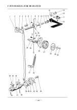
Page 22: ...F STITCH REGULATOR MECHANISM 20 20 ...
Page 24: ...G LOWER SHAFT FEEDING SHAFT MECHANISM 22 22 ...
Page 27: ...H HOOK SADDLE MECHANISM 25 25 ...
Page 29: ...I OIL LUBRICATION MECHANISM 27 27 ...
Page 31: ...J ACCESSORIES 29 29 ...


