14
English
How to make the batteries perform longer.
(1) Recharge the batteries before they become completely
exhausted.
When you feel that the power of the tool becomes
weaker, stop using the tool and recharge its battery. If
you continue to use the tool and exhaust the electric
current, the battery may be damaged and its life will
become shorter.
(2) Avoid recharging at high temperatures.
A rechargeable battery will be hot immediately after
use. If such a battery is recharged immediately after
use, its internal chemical substance will deteriorate, and
the battery life will be shortened. Leave the battery and
recharge it after it has cooled for a while.
CAUTION
○
If the battery is charged while it is heated because
it has been left for a long time in a location subject to
direct sunlight or because the battery has just been
used, the charge indicator lamp of the charger lights
for 0.3 seconds, does not light for 0.3 seconds (o
ff
for
0.3 seconds). In such a case,
fi
rst let the battery cool,
then start charging.
○
When the charge indicator lamp
fl
ickers (at 0.2-second
intervals), check for and take out any foreign objects in
the charger’s battery connector. If there are no foreign
objects, it is probable that the battery or charger is
malfunctioning. Take it to your authorized Service
Center.
○
Since the built-in micro computer takes about
3 seconds to con
fi
rm that the battery being charged with
UC18YSL3 is taken out, wait for a minimum of 3 seconds
before reinserting it to continue charging. If the battery
is reinserted within 3 seconds, the battery may not be
properly charged.
PRIOR TO OPERATION
WARNING
Pull out battery before carrying out any adjustment,
servicing or maintenance.
When
fi
nished with a job, pull out the battery.
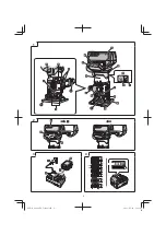
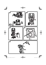
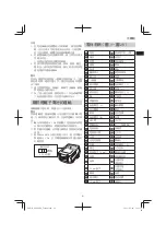
1. Removing and inserting the battery (Fig. 2)
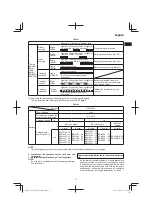
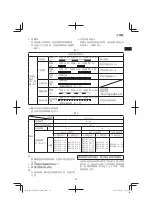
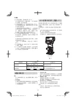
2. Remaining battery indicator (Fig. 4)
3. Installation direction of base ass’y (Fig. 5)
The switch position can be changed according to
preference by reversing the installation direction of the
base ass’y.
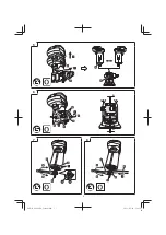
4. Fix strength adjustment method (Fig. 6)
If there is a decline in the
fi
x strength, adjust as follows.
Tilt the lock lever towards the
fi
xed side, and tighten
a
fi
xing nut (two locations) using the socket wrench
(8 mm).
Fix it so that upper and lower spaces “A” of the base
ass’y are equal.
NOTE
If the operation load of the lock lever is too heavy, there
is too much
fi
xed strength.
As this situation may damage parts, each
fi
xing nut
(two locations) should be loosened to readjust the
fi
xed
strength.
INSTALLING AND REMOVING BITS
WARNING
Be sure to switch power OFF and pull out the battery to
avoid serious trouble.
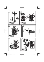
1. Installation using the lock pin (Fig. 7)
(1) Remove the base ass’y from the body.
(2) Deeply insert the bit into collet cone hole. (The distance
is 15 mm or more from side of collet nut.
(3) With the bit inserted and pressing the lock pin holding
the shaft, use the 23 mm wrench to
fi
rmly tighten the
collet nut in a clockwise direction (viewed from under the
tool). (
Fig. 7
)
(4) Fit the removed base ass'y to the rack provided on the
body's outer housing after adjusting the pinion of the
base ass'y thereto. Then tilt the lock lever towards the
fi
x
side, and
fi
x the base ass'y securely.
When removing the bits, do so by following the steps for
installing bits in reverse order.
CAUTION
○
Ensure that the collet nut is
fi
rmly tightened after inserting
a bit. Failure to do so will result in damage to the collet
cone.
○
Ensure that the lock pin is not inserted into the shaft after
tightening the collet nut. Failure to do so will result in
damage to the collet cone, lock pin and shaft.
2. Install without using the lock pin (Fig. 8)
(1) Remove the base ass’y from the body.
(2) Deeply insert the bit into collet cone hole. (The distance
is 15 mm or more from side of collet nut.
(3) Use a 13 mm wrench to secure the shaft, and securely
tighten the collet nut with the included wrench.
(4) Fit the removed base ass'y to the rack provided on the
body's outer housing after adjusting the pinion of the
base ass'y thereto. Then tilt the lock lever towards the
fi
x
side, and
fi
x the base ass'y securely.
When removing the bits, do so by following the steps for
installing bits in reverse order.
CAUTION
○
Ensure that the collet nut is
fi
rmly tightened after inserting
a bit. Failure to do so will result in damage to the collet
cone.
3. Exchanging the collet cone (Fig. 9)
(1) Securing the shaft, remove the collet nut, and exchange
the collet cone.
(2) Attach the nut, insert the bit, and tighten the nut.
NOTE
When tightening the collet nut, make sure that the bit is
inserted.
Otherwise, the collet cone may become misshapen.
HOW TO USE THE TRIMMER
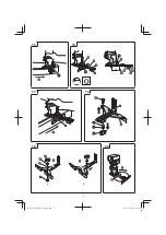
1. Adjusting depth of cut (Fig. 10)
(1) Place the tool on a
fl
at wood surface.
(2) Tilt the lock lever towards the remove side, and turn
knob bolt (A) to lower the unit until the tip of the bit lightly
touches the material. In this position, the scale on the
upper end of the base ass'y can be read.
(3) Turn knob bolt (A) upwards to adjust the scale to the
desired cutting depth according in accordance with the
position read.
00Book̲M3608DA̲Taiwan.indb 14
00Book̲M3608DA̲Taiwan.indb 14
2021/07/29 16:25:34
2021/07/29 16:25:34


