CameraLink Line Scan Camera
·
User Manual
39
1
2
3
4
5
6
7
8
9
10
11
12
Input TTL Signal
12-Pin Interface
Gnd
External Gnd
Gnd
3.3V
Camera
3.3V
10KΩ
8.2KΩ
Gnd
To
Fpga
120Ω
Disconnect
I/O IN+
Receiver
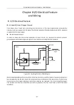
Figure 8-3
Inputting LVTTL Signal
8.1.2 Line 1/Line 4 Output Circuit
The camera has 2 output pins, including Line 1 and Line 4. The output signal cable connects the
camera via 12-pin power and I/O cable. The RS-422 standard, RS-644 standard and LVTTL standard
is applied to this output signal.
RS-422 Standard Output
In order to make sure the normal operation of output circuit, it is required to connect camera’s
ground signal with external ground signal. The output interface can be connected to the RS-422
bus structure as a master dispenser.
1
2
3
4
5
6
7
8
9
10
11
12
12-Pin Interface
Gnd
3.3V
Camera
To
Fpga
I/O OUT 1+
I/O OUT 1-
Gnd
External Gnd
To RS-422 Input
Driver
Figure 8-4
Outputting RS-422 Signal


