ID3000 Series Smart Code Reader User Manual
8
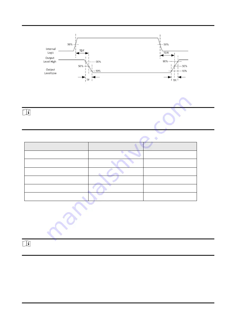
Figure 3-4 Output Logic Level
When the external voltage and resistance is 12 VDC and 1 KΩ respectively, output electrical
feature is as follows.
Note
If the external voltage and resistance change, the corresponding current of output signal and
output logic level low may differ.
Table 3-2 Output Electrical Feature
Parameter Name
Parameter Symbol
Value
Output Logic Level Low
VL
212 mV
Output Logic Level High
VH
11.8 VDC
Output Falling Delay
TDF
0.4 μs
Output Rising Delay
TDR
0.4 μs
Output Falling Time
TF
0.4 μs
Output Rising Time
TR
0.4 μs
3.3 Input Signal Wiring
The device can receive the external input signal via I/O interface, and here we take LineIn 0 as an
example to introduce input signal wiring.
Note
Input signal wiring may differ by external device types.


