SC2000 Series Vision Sensor User Manual
3
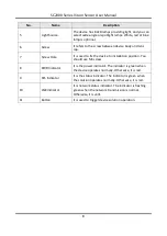
No.
Name
Description
5
Light Source
The device has 8 LED lamps providing light, and you can
select wide-angle or spotlight lamps. White, red or blue
lamp is optional.
6
Screw
It refers to the screw between device body and lens
cap.
7
Screw Hole
It is used to fix the device to installation position. You
should use M4 screw.
8
PWR Indicator
It is the power indicator. The indicator is green when
the device operates normally. Otherwise, it is red.
9
STS Indicator
It is the status indicator. The indicator is green when
the solution operates normally. Otherwise, it is red.
10
LNK Indicator
It is network status indicator. The indicator is flashing
green when the network transmission is normal.
Otherwise, it is unlit.
11
Button
It is used to trigger device solution operation.

