background image

SC2000 Series Vision Sensor User Manual 

70 

10.1.2 Set Technician Permission and Password 

When logging in as admin, you have the permission to set technician password and its permission 
to different operation modules. 

Note 


The admin can access to all operation and tool modules via web, and assign module operation 
permission to technician, while technician can access to and set module parameters assigned by 
the admin only. 


If the technician permission is not enabled, you cannot log in as technician via web. 


The default technician password is Abc1234. 


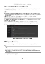
Click System → User Management, enable Open Module to enable technician permission, enter 
Technician PWD, and click OK
Check Assign Permission to Technician in respective module to assign module operation 
permission to technician, or go to Solution → Finish → Permission Assignment to assign 
permission to the technician. 


Figure 10-2 Set Technician Permission and Password   

10.2 Upgrade Firmware 

Firmware update allows you to view current device firmware version and update firmware. 

Steps   

Note 


Make sure the device and solution stop operation when updating the firmware. 


After updating, the device will automatically reboot, and the web will automatically jump to 
login interface. 


1. Click System → Firmware Upgrade

Summary of Contents for SC2000 Series

Page 1: ...SC2000 Series Vision Sensor User Manual ...

Page 2: ...Y SATISFACTORY QUALITY OR FITNESS FOR A PARTICULAR PURPOSE THE USE OF THE PRODUCT BY YOU IS AT YOUR OWN RISK IN NO EVENT WILL HIKROBOT BE LIABLE TO YOU FOR ANY SPECIAL CONSEQUENTIAL INCIDENTAL OR INDIRECT DAMAGES INCLUDING AMONG OTHERS DAMAGES FOR LOSS OF BUSINESS PROFITS BUSINESS INTERRUPTION OR LOSS OF DATA CORRUPTION OF SYSTEMS OR LOSS OF DOCUMENTATION WHETHER BASED ON BREACH OF CONTRACT TORT I...

Page 3: ...ant to part 15 of the FCC Rules These limits are designed to provide reasonable protection against harmful interference in a residential installation This equipment generates uses and can radiate radio frequency energy and if not installed and used in accordance with the instructions may cause harmful interference to radio communications However there is no guarantee that interference will not occ...

Page 4: ... product documentation for specific battery information The battery is marked with this symbol which may include lettering to indicate cadmium Cd lead Pb or mercury Hg For proper recycling return the battery to your supplier or to a designated collection point For more information see www recyclethis info Symbol Conventions The symbols that may be found in this document are defined as follows Symb...

Page 5: ...e risk of fire or electric shock do not let the device get wet or damp Do not drop objects onto the device and avoid vigorous vibration Keep the device away from magnetic interference Do not use the device in extremely heat extremely cold dusty environment corrosive environment or high humidity environment Do not aim the device lens at objects of strong light such as the sun and incandescent lamp ...

Page 6: ...turer for processing The company does not bear any liability for accidental damage during transportation caused by non original packaging This device is a precision electronic device no components can be maintained by user do not disassemble the device arbitrarily Cleaning Do not touch the image sensor directly If the sensor needs to be cleaned use a clean rag and wet it with alcohol then gently w...

Page 7: ...Installation 13 5 1 Installation Preparation 13 5 2 Install Device 13 5 3 Install Client Software 14 Chapter 6 Network Settings 15 6 1 Set PC Network 15 6 2 Connect Camera to Client Software 16 6 3 Set Camera Network 16 Chapter 7 Access Device via Web Browser 17 7 1 Login 17 7 2 Web Layout Introduction 18 Chapter 8 Solution Settings 21 8 1 Camera Settings 21 8 1 1 Set Frame Rate 21 8 1 2 Set Gain ...

Page 8: ... Settings 30 8 4 1 Feature Matching 30 8 4 2 Fixture Settings 35 8 4 3 Find Circle 36 8 4 4 Find Line 40 8 4 5 Find Edge Width 44 8 4 6 Brightness Measure 47 8 4 7 Blob 49 8 4 8 L2L Measure 53 8 4 9 Format Tool 55 8 4 10 Logic Tool 56 8 5 Communication Settings 57 8 5 1 UDP 57 8 5 2 TCP Client 58 8 5 3 TCP Server 59 8 5 4 Serial 60 8 5 5 IO Communication 61 8 5 6 FTP 62 8 6 Solution Completion 63 ...

Page 9: ...Set Technician Permission and Password 70 10 2 Upgrade Firmware 70 10 3 Synchronize Time 71 10 4 Restore Defaults 72 10 5 View Log 73 10 6 View System Version 73 Chapter 11 FAQ Frequently Asked Question 74 11 1 Why the client software cannot list cameras 74 11 2 Why the image is not smooth in live view 74 11 3 Why the image is very dark 74 11 4 Why there is no image in live view 74 ...

Page 10: ...e to machine vision detection It uses sensor and optical component to acquire object image and adopts built in location and measurement algorithm to detect object dimension location etc The detection results can be output via UDP TCP FTP and other communication methods You can configure and operate different solutions of the vision sensor via web ...

Page 11: ...tween the device and cable and thus avoiding influence caused by vibration 2 Focus Knob It is used to adjust focal length manually 3 OK NG Indicator It indicates the result of solution The green indicator lights when the solution result is OK The red indicator lights when the solution result is NG When switching solutions the indicators both light After switching the indicators both are unlit 4 Le...

Page 12: ...the device to installation position You should use M4 screw 8 PWR Indicator It is the power indicator The indicator is green when the device operates normally Otherwise it is red 9 STS Indicator It is the status indicator The indicator is green when the solution operates normally Otherwise it is red 10 LNK Indicator It is network status indicator The indicator is flashing green when the network tr...

Page 13: ...ut or output 3 DO_2 Line 7 signal line Opto isolated output 4 RS232TX RS232 serial port output 5 RS232RX RS232 serial port input 6 MDI0 Fast Ethernet signal MDI0 7 MDI1 Fast Ethernet signal MDI1 8 DO_0 Line 5 signal line Opto isolated output 9 I O_0 Line 2 signal line Can be configured as input or output 10 DO_1 Line 6 signal line Opto isolated output 11 GND Signal ground Direct current power supp...

Page 14: ... O cable to wire the device It is recommended to use the supplied 17 pin cable The 6th 7th 14th and 15th pin have been made as RJ45 connector The lines of other pins should be wired according to the actual demands Figure 3 2 17 Pin Cable 3 2 RS 232 Interface The device supports RS 232 serial port output and you can set serial port parameters in client software The solution result will be transmitt...

Page 15: ...SC2000 Series Vision Sensor User Manual 6 Figure 3 4 25 Pin Interface Table 3 2 RS 232 Interface Description Serial Port Type Pin No Name 9 Pin Interface 2 RX 3 TX 5 GND 25 Pin Interface 2 TX 3 RX 7 GND ...

Page 16: ...device s Line 0 1 is input signal and Line 2 3 4 are bi directional I O s that can be set as input signal The internal circuit of input signal is as follows Note The maximum input current of input signal is 25 mA Figure 4 1 Internal Circuit of Input Signal Figure 4 2 Input Logic Level ...

Page 17: ... Input Rising Delay TDR 1 3 μs to 3 5 μs Note VCC stands for Volt Current Condenser and it is the device s input voltage The breakdown voltage is 36 VDC and keep voltage stable 4 2 Output Signal The device s Line 5 6 7 are output signals and Line 2 3 4 are bi directional I O that can be set as output signal The type of output signal can be set as PNP or NPN via web parameter When the output signal...

Page 18: ...Circuit of NPN Output Signal Figure 4 5 Output Logic Level When the external voltage and resistance is 12 VDC and 1 KΩ respectively opto isolated output electrical feature is as follows Note With different external voltage and resistance the corresponding current and output logic level low may have small change ...

Page 19: ... Rising Time TR 0 4 μs 4 3 Input Signal Wiring The device can receive external input signal via I O interface and here we take one line as an example to introduce input signal wiring Note Input signal wiring may differ with different types of external devices PNP Device Note It is recommended to use 330 Ω pull down resistor Figure 4 6 Input Signal Connecting to PNP Device NPN Device Note If the VC...

Page 20: ...Output Signal Wiring The device can output signal to external device via I O interface and here we take one line as an example to introduce output signal wiring Note Output signal wiring may differ with different types of external devices You can set device output signal as NPN or PNP via web When the device output signal is PNP it is recommended to use 330 Ω pull down resistor if NPN device is co...

Page 21: ...NP When the device output signal is NPN its wiring with PNP device is as follows Figure 4 10 Device Outputs NPN Note When the device s output signal is set as NPN the voltage of VCC should not higher than that of PWR Otherwise the device s output signal may have exception ...

Page 22: ...cap You can also use polarization lens cap that needs to be purchased separately 4 Light Source 1 It refers to the supplied white light source You can also use red or blue light source that needs to be purchased separately 5 M4 Screw 4 It refers to the supplied M4 screw that is used to fix the device to installation position 5 2 Install Device Before You Start Make sure the device in the package i...

Page 23: ...ch_support hikrobot com to get client software installation package The graphic user interface may differ by different versions of client software you use 1 Double click the installation package to start installing the client software 2 Select the language 3 Read and check Terms of the License Agreement 4 Click Start Setup 5 Select installation directory and click Next Figure 5 1 Installation Inte...

Page 24: ...ath and interface may differ Please refer to the actual condition Steps 1 Go to PC network settings page Start Control Panel Network and Internet Network and Sharing Center Change adapter settings 2 Select NIC and set the IP obtainment mode Select Obtain an IP address automatically to get an IP address of the PC automatically Note Enter ipconfig in Run window in your PC and then you can view the P...

Page 25: ...onnecting the camera to it Double click the camera name in the device list or click to connect the camera to the client 6 3 Set Camera Network You can set and operate the camera in the client software only when the camera is in the same network segment with the PC where the client software is installed Steps 1 Double click the client software to run it 2 Click in device list to search the device 3...

Page 26: ...owser and you can configure and operate different solutions of vision sensor as well as set system parameters 7 1 Login Before You Start Go to device information area of the client software to view the device IP address Figure 7 1 Device IP Address Steps 1 Open the web browser and enter the IP address of the device Figure 7 2 Login Interface ...

Page 27: ...nd switch different saved solutions and view device information This module includes solution control solution operation information solution management device information and image display Figure 7 3 Basic Information Module Table 7 1 Description of Basic Information Module No Area Name Description 1 Solution Control It is used to control solution and display solution operation result 2 Solution ...

Page 28: ...solution operation result 2 Solution Settings It is used to set up solution It includes Camera Tool Output and Finish 3 Image Display It is used to display the operation result after executing current solution 4 Operation History It is used to display module operation result Only recent 10 history results are displayed 5 Time Calculation It is used to calculate and display the time cost by algorit...

Page 29: ...SC2000 Series Vision Sensor User Manual 20 Figure 7 5 System Module ...

Page 30: ...f the parameter is smaller than the max frame rate of the device the exposure will be ignored The max frame rate of the device can reach the configured frame rate If the parameter is larger than the max frame rate of the device and without considering other factors the device frame rate cannot reach the configured frame rate and can reach the max frame rate of the device itself only Figure 8 1 Set...

Page 31: ... Exposure Mode to select exposure mode and enter exposure time OFF When the exposure mode is set as OFF and enter exposure time manually ONCE When the exposure mode is set as ONCE the device adjusts the exposure time automatically once according to the image brightness CONTINUOUS When the exposure mode is set as CONTINUOUS the device adjusts the exposure time continuously according to the image br...

Page 32: ...an that of exposure It only takes effect when selectingFLASH_STROBE as Flash Mode Advance It refers to the time when light source starts to light is early than that of exposure Figure 8 2 Set Light Source 8 1 5 Set Image Go to Solution Camera Image to set image related parameters Pixel Format It currently only supports the pixel format of MONO8 Width It refers to the image width and you can adjust...

Page 33: ...age height height deviation height max value W H Conversion This parameter is 1 by default and it sets the relation between image coordinates and physical coordinates that is a pixel on the image represents the length in actual physical position Gamma Gamma correction provides a non linear mapping mechanism When Gamma value is between is 0 and 1 image brightness increases and dark area becomes bri...

Page 34: ...es images via its internal signals External Trigger Mode In this mode the device acquires images via external signals like software signal hardware signal communication string etc The trigger source of external trigger mode includes software trigger hardware trigger button trigger and communication trigger 8 2 2 Enable Internal Trigger Mode Go to Solution Camera Trigger Trigger Mode to select OFF ...

Page 35: ...rigger Mode 2 Select SOFTWARE as Trigger Source 3 Click Software Trigger in Software Trigger to send trigger commands 4 Enter Delay time according to actual demands Figure 8 6 Set and Execute Software Trigger Mode Set and Execute Hardware Trigger Mode Steps 1 Select ON as Trigger Mode 2 Select LINE0 LINE1 LINE2 LINE3 or LINE4 as Trigger Source ...

Page 36: ...en the level signal sent by external device is in rising edge the device receives trigger signal and starts to acquire images Falling Edge It means that when the level signal sent by external device is in falling edge the device receives trigger signal and starts to acquire images Level High The level high of the trigger signal is valid As long as the trigger signal is in level high the device is ...

Page 37: ...lect line or button as Trigger Source Select ON as Trigger Mode select LINE0 LINE1 LINE2 LINE3 LINE4 or BUTTON as Trigger Source and enter Filter Time according to actual demands Figure 8 9 Set Filter Time Set Trigger Delay The trigger delay function allows the camera to add a delay between the receipt of trigger signal and the moment the trigger becomes active Select ON as Trigger Mode select LIN...

Page 38: ...s Trigger Mode select BUTTON as Trigger Source You can also enter Filter Time and Delay according to actual demand Figure 8 11 Enable Button Trigger Mode 8 2 6 Enable Communication Trigger Mode The device also supports triggering by receiving communication string Select ON as Trigger Mode select COMMUNICATION as Trigger Source and enter String and Delay according to actual demands ...

Page 39: ...tings The tool settings have 2 types of tools including location tools and check tools You can use Match Trait Find Circle Blob module and others to extract the features of detected objects You can also use Detect Distance Measure Brightness Measure L2L and others to measure detected objects Go to Solution Tool and double click the tool you want to use 8 4 1 Feature Matching This tool uses the edg...

Page 40: ...tangle only Fixture After enabling it you can subscribe fixture tool See Fixture Settings for details Note If you want to use fixture tool in feature matching you should set fixture tool first Figure 8 14 Feature Matching Feature Template There are 2 ways to create feature template for feature matching Go to Solution Tool Template and click Upload to upload local template to create feature templat...

Page 41: ...old according to actual demands Note Feature Scale refers to the fineness level of the feature and it can be set between 0 and 200 The larger the feature scale the sparser the extracted feature edge points are It is recommended to use the default value 0 that is adaptive roughness scale Threshold refers to the gray value difference between the feature point and the surrounding background and it ca...

Page 42: ... Ignored Angle It is the angle range of searched targets The edited template is the reference Scale Zoom in and zoom out with same scale It is applied for the target and template with certain percentage Max Overlap Rate The higher the overlap rate the larger the overlap area that can be tolerated The increase of overlap rate may reduce the search speed and introduce false detections Sort You can s...

Page 43: ...y Angle Judge by Scale Judge by Score Judge by Match Point X Judge by Match Point Y Judge by Center Point X Judge by Center Point Y and enter corresponding range according to actual demands In Image Display click to display or not display image detection area fuzzing match results and fuzzing match point Click to edit OK color NG color and transparency In OSD enable Display Test to set text s colo...

Page 44: ...ate matching result And then the coordinate and rotation deviation of ROI detection frame can be realized according to the relative deviation of feature matching result and reference position Origin X Link the matching point of template to the origin point of position deviation Origin Y Link the matching point of template to the origin point of position deviation Reference Angle Link the matching ...

Page 45: ...ure 8 19 Result Display 8 4 3 Find Circle This tool detects multiple edge points first and then fits them into a circle It is used to locate and measure the circle Image Source By default the image source is the images acquired by the device Shape You can use to maximize the ROI Region of Interest or use to draw the ROI Note Before drawing ROI you need to stop solution operation After drawing ROI ...

Page 46: ... the radius of the target circle must be within this range Search Mode It has three modes including Max Contrast Max Radius and Min Radius Max Contrast refers to only edge points of the largest gradient threshold within the scan range is detected and the circle is fitted Max Radius refers to only edge points of the longest distance from the circle center within the scan range is detected and the c...

Page 47: ...ect the accuracy of the edge location or even lose edge This parameter value needs to be set based on the actual situation Caliper Quantity It is used to scan ROI area quantity of edge points Ignored Point It means that the number of minimum points that have high error to be excluded from fitting In general if there is a great number of points excluded from fitting its value should be set higher F...

Page 48: ... Settings Result Display In display area you can set different judge methods of image detection result including radius center X center Y fit error etc In Judge Method enable Judge by Radius Judge by Center X Judge by Center Y Judge by Fit Error Judge by Fit Points and enter corresponding range according to actual demands In Image Display click to display or not display circle result center point ...

Page 49: ... and then fits into a line Image Source By default the image source is the images acquired by the device Shape You can use to maximize the ROI Region of Interest or use to draw the ROI Note Before drawing ROI you need to stop solution operation After drawing ROI you need to click Apply The ROI can be rectangle only Fixture After enabling it you can subscribe fixture tool See Fixture Settings for d...

Page 50: ...hin scan area Last Line refers to find the set of edge points that have the closest distance with ending point and them into a line within scan area Search Direction It has two directions including Top to Bottom and Left to Right Edge Polarity It has three modes including Light to Dark Dark to Light and Any Light to Dark refers to the transition from the area with a low gray value to the edge of t...

Page 51: ...oints excluded from fitting its value should be set higher For better results it is recommended to use it in combination with the parameter of distance to remove Removed Distance The max pixel distance from the outliers to the fit circle The smaller the value the more the exclusion points Projection Width It means that the area width of edge point ROI You can increase this parameter value within a...

Page 52: ...cluding fit points and angle In Judge Method enable Judge by Fit Points Judge by Angle and enter corresponding range according to actual demands In Image Display click to display or not display line result and detection area Click to edit OK color NG color and transparency In OSD enable Display Test to set text s color front size transparency position X and position Y ...

Page 53: ...s the images acquired by the device Shape You can use to maximize the ROI Region of Interest or use to draw the ROI Note Before drawing ROI you need to stop solution operation After drawing ROI you need to click Apply The ROI can be rectangle only Fixture After enabling it you can subscribe fixture tool See Fixture Settings for details Note If you want to use fixture tool in detecting distance you...

Page 54: ...dge This parameter value needs to be set based on the actual situation Contrast Threshold It is also called gradient threshold and its range is from 0 to 255 The edge point whose gradient threshold is larger than this value can be detected The larger the value the stronger noise resistibility the smaller the number of edges obtained and even the target edge points are filtered out Edge 0 Polarity ...

Page 55: ...ting point within the detection range Last edge means the edge pair that its center has farthest spacing to the search starting point within the detection range Closest means that the set of edge pair that has closest width to ideal width within the detection range Keep Away means that the set of edge pair that has least closest width to ideal width within the detection range All means that detect...

Page 56: ...color and transparency In OSD enable Display Test to set text s color front size transparency position X and position Y Figure 8 28 Result Display 8 4 6 Brightness Measure This tool returns the gray mean value and the gray standard deviation of all the pixels in the ROI of the object to be measured When using the ROI can be drawn at the ideal measurement position Image Source By default the image ...

Page 57: ...e methods of image detection result including max value min value mean value standard deviation etc In Judge Method enable Judge by Max Value Judge by Min Value Judge by Mean Value Judge by Standard Deviation Judge by Contrast and enter corresponding range according to actual demands You can also enable Reverse Result to reverse result In Image Display click to display or not display detection are...

Page 58: ...t object in the image such as presence quantity position shape direction and topological relation between Blobs Image Source By default the image source is the images acquired by the device Shape You can use to maximize the ROI Region of Interest or use to draw the ROI Note Before drawing ROI you need to stop solution operation After drawing ROI you need to click Apply The ROI can be rectangle onl...

Page 59: ...ion Single Threshold Double Threshold and Auto Threshold Polarity It has 2 modes including Darker than Background and Brighter than Background Darker than Background means that the feature image pixel value is lower than the background pixel value Brighter than Background means that the feature image pixel value is higher than the background pixel value Note This parameter takes effect when select...

Page 60: ...ute pixel offset between the Blob centroid and the minimum area of the Blob circumscribed rectangle Sort It includes By Area From Large to Small Sort from Top to Down Sort from Left to Right 2D Sort Sort by Angle and No Sort Connectivity In image processing the object we are interested in is usually a combination of interconnected pixels Therefore in order to obtain an area we must calculate all t...

Page 61: ...ob area centroid X centroid Y angle center X center Y etc In Judge Method enable Judge by Blob Quantity Judge by Blob Area Judge by Centroid X Judge by Centroid Y Judge by Angle Judge by Center X Judge by Center Y Judge by Blob Height Judge by Blob Weight Judge by Circumference Judge by Long Axis Judge by Short Axis Judge by Circularity Judge by Rectangularity and enter corresponding range accordi...

Page 62: ...ance is calculated by the average distance from four end points of the line to another line You can enter the information of 2 lines to be measured and the basic parameters are shown below Input Method It includes by line and by coordinate Line If you select by line as input method you need to link the result of finding line X Coordinate of Start Point If you select by coordinate as input method y...

Page 63: ...tween two lines Figure 8 35 L2L Measure Result Display In display area you can set different judge methods of image detection result including angle distance intersection point X and intersection point Y In Judge Method enable Judge by Angle Judge by Distance Judge by Intersection Point X Judge by Intersection Point Y and enter corresponding range according to actual demands In Image Display click...

Page 64: ...double click Format to open it In basic parameter interface click to subscribe data that is needed formatting or enter it directly and then click OK Note The max byte allowed for formatting is 1024 bytes When configuring multiple data if one of data cannot be obtained format exception may occur In display interface enable Display Test to set text s color front size transparency position X and posi...

Page 65: ...ic operation Go to Solution Output Logic Tool Logic and double click Logic to open it Select AND OR NOT NAND or NOR as Logical Operation Type and click to link data source or enter data directly You can also click to add multiple data Note If there is logic module in the solution you can go to Solution Finish Result to link the result of logic tool to the solution ...

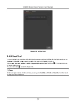
Page 66: ...o select different communication tools according to actual demands 8 5 1 UDP In basic parameter interface set output information as Input Variable and enter Local IP Local Port Target IP and Target Port according to actual solution demands Note Input Variable currently supports format result data only In display interface enable Display Test to set text s color front size transparency position X a...

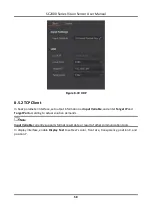
Page 67: ...put information as Input Variable and enter Target IP and Target Port according to actual solution demands Note Input Variable currently supports format result data or result of other communication tools In display interface enable Display Test to set text s color front size transparency position X and position Y ...

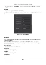
Page 68: ... output information as Input Variable and enter Local IP and Local Port according to actual solution demands Note Input Variable currently supports format result data or result of other communication tools In display interface enable Display Test to set text s color front size transparency position X and position Y ...

Page 69: ...d enter Serial Port Mode Baud Rate Parity Bit and Stop Bit according to actual solution demands Note Data Bit is 8 by default and it can be read only Input Variable currently supports format result data or result of other communication tools In display interface enable Display Test to set text s color front size transparency position X and position Y ...

Page 70: ...ode to add line to IO communication Note One IO module can set multiple IO statuses but one solution supports one IO module at most Output Condition It links the results of previous module Duration It refers to the duration of outputting IO signal Delay Time It refers to the waiting time after the vision sensor receives IO output signal Valid Electrical Level The default value means the level low ...

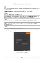
Page 71: ...ure 8 43 IO Communication 8 5 6 FTP In FTP communication set the image file of the device as File Info and set the previous module status as Input Status When using FTP as communication tool you need to set target IP target port user name password image saving frame index result start tag and end tag and separator according to actual solution demands Target IP and Port It refers to the IP and Port...

Page 72: ...nk input status result Start Tag and End Tag It refers to the start and end tag of image name You can enter lowercase and uppercase letter digit and _ Separator It is used to separate each content like image frame number start and end tag You can enter lowercase and uppercase letter digit and _ Figure 8 44 FTP 8 6 Solution Completion The finish module can set solution name and save solution set so...

Page 73: ...to check All to open all modules to technician or check specific one to assign it to technician Note You need to go to System User Management Technician Open Module to enable technician permission first In Result if you have used logic tool in your solution you can view and link the result of logic module to the solution Note You can link only one logic module result at one time After editing solu...

Page 74: ...on operation It displays the operation status of the solution When logic tool is not selected the system displays the result of all modules operation and calculation If the result is 0 the system displays NG Otherwise the system displays OK When logic tool is selected the system displays the result of logic tool you selected 9 2 View Solution Status The solution operation information module record...

Page 75: ...cquisition NG refers to the total quantity of image with NG result from device powering on to now Figure 9 2 View Solution Status 9 3 Manage Solution The solution management module can set and switch among multiple solutions Figure 9 3 Manage Solution Table 9 2 Icon Description Icon Description You can search solution here if there are many solutions Click it to upload local solution to the device...

Page 76: ...Tool to select communication tool to receive strings and set related parameters DI COMM refers to use both digital IO and communication string to switch solution OFF refers to disable solution switch function 9 4 View Camera Info In device information area you can view the device serial number MAC address subnet mask firmware and edit user ID or IP address Note Before editing IP address you need t...

Page 77: ...n Icon Description Click it to download the image to the PC The default format is JPG Click it to zoom out the displayed image It displays the current image scaling ratio Click it to zoom in the displayed image Click it to set image size as 1 1 Figure 9 5 Operate Image ...

Page 78: ...operation modules Note Only the admin has the permission to access to user management module If you log in as technician there is no this module The admin can access to all operation and tool modules via web and assign module operation permission to technician while technician can access to and set module parameters assigned by the admin only The default admin password is Abc1234 Click System User...

Page 79: ...ician password is Abc1234 Click System User Management enable Open Module to enable technician permission enter Technician PWD and click OK Check Assign Permission to Technician in respective module to assign module operation permission to technician or go to Solution Finish Permission Assignment to assign permission to the technician Figure 10 2 Set Technician Permission and Password 10 2 Upgrade...

Page 80: ...at of local PC or server It consists of auto mode by Network Time Protocol NTP server and manual mode Steps 1 Click System Time Sync 2 Select time synchronization method Click Manual select date and time from the calendar or check Sync With PC to synchronize the time of the device with that of the local PC Click NTP enter Server Add NTP Port and Interval Hour 3 Click Save Figure 10 4 Manual Time S...

Page 81: ...llows you to restore the device to factory settings Note Device solutions will be deleted after restoring defaults You may log in again and the admin password will be the default one Abc1234 Click System Restore Factory enter Admin Password and click OK to restore defaults Figure 10 6 Restore Defaults ...

Page 82: ...o view device and web operation records Click System Log click Refresh and view log information Figure 10 7 View Log 10 6 View System Version About and help module allows you to view system version Click System About and Help and view system version Figure 10 8 View System Version ...

Page 83: ...same network segment 11 2 Why the image is not smooth in live view Reason The network transmission speed is not up to 100 Mbps Solution Check if the network transmission speed is up to 100 Mbps 11 3 Why the image is very dark Reason The brightness of light source is not enough Exposure and gain values are too small Solution Increase the brightness of light source or use brighter lamps Increase exp...

Page 84: ...Series Vision Sensor User Manual 75 The network transmission speed is not up to 100 Mbps Solution Send trigger signal to device or disable trigger mode Check if the network transmission speed is up to 100 Mbps ...

Page 85: ...UD17329B ...

Reviews: