SC2000E(Mini) Series Vision Sensor Quick Start Guide
17
7.2.1 Input Wiring
Note
Input signal wiring may differ by external device types.
PNP Device
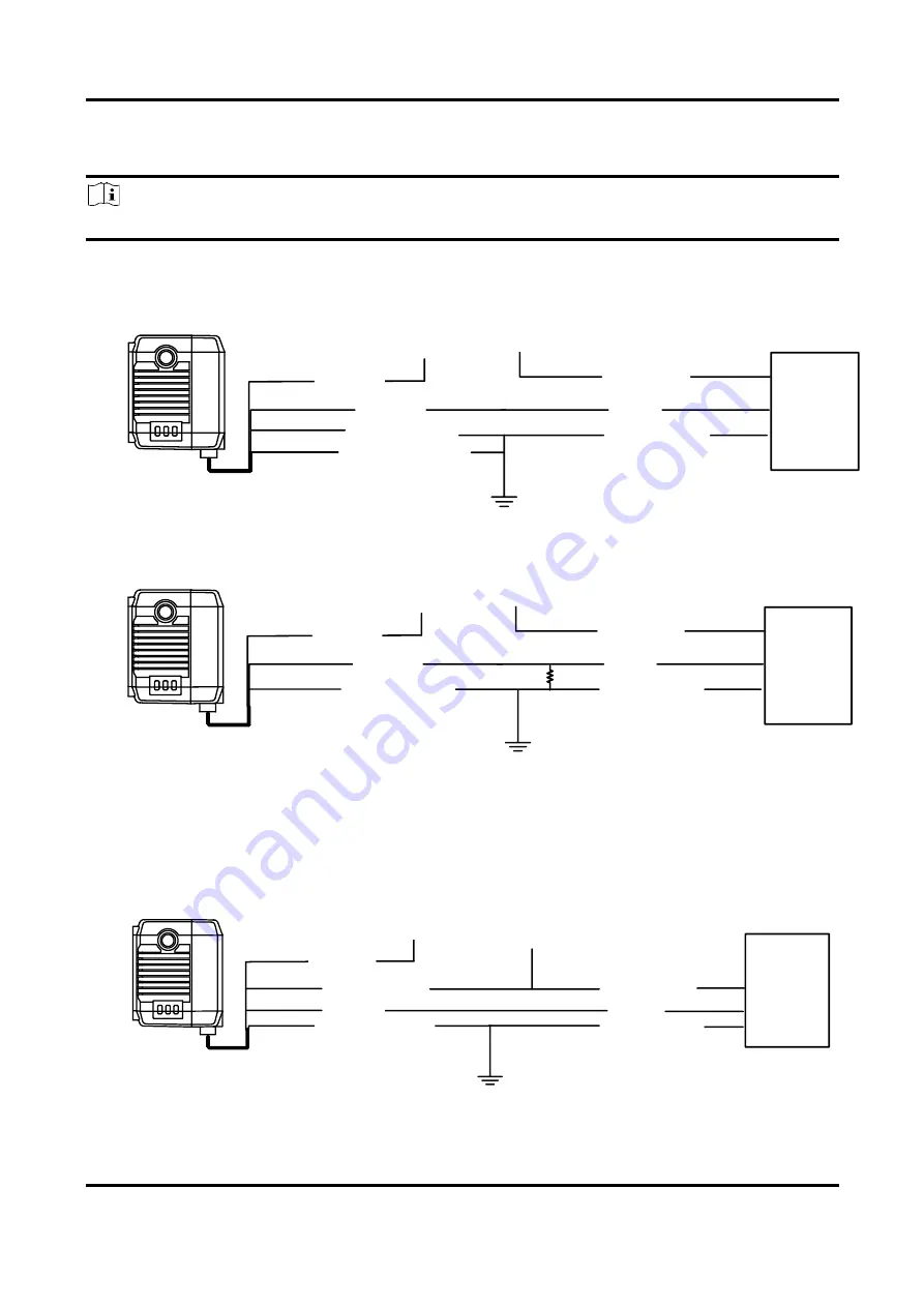
If you use the pull-down resistor of the supplied 17-pin cable, the wiring is shown below.
Input Signal
Device Power
PWR
Pull-Up and Pull-Down
Resistor
PNP
Device
PNP Device Power
PNP Power Ground
Signal Line
VCC
GND of PWR and VCC
Device Power Ground
Figure 7-4 Input Signal Connecting to PNP Device (Pull-Down Resistor of 17-Pin Cable Used)
If you use external pull-down resistor, it is recommended to use 1 KΩ pull-down resistor.
Input Signal
Device Power
PWR
Device Power Ground
PNP
Device
PNP Device Power
PNP Power Ground
Signal Line
VCC
GND of PWR and VCC
Figure 7-5 Input Signal Connecting to PNP Device (External Pull-Down Resistor Used)
NPN Device
If the VCC of NPN device is 12 VDC or 24 VDC, and the pull-up resistor of the supplied 17-pin cable
is used.
Device Power
PWR
Device Power Ground
NPN
Device
NPN Device Power
VCC
GND of PWR and VCC
Pull-Up and Pull-Down
Resistor
Input Signal
Signal Line
NPN Power Ground
Figure 7-6 Input Signal Connecting to NPN Device (Pull-Up Resistor of 17-Pin Cable Used)


