background image

SC2000E(Mini) Series Vision Sensor Quick Start Guide 

10 


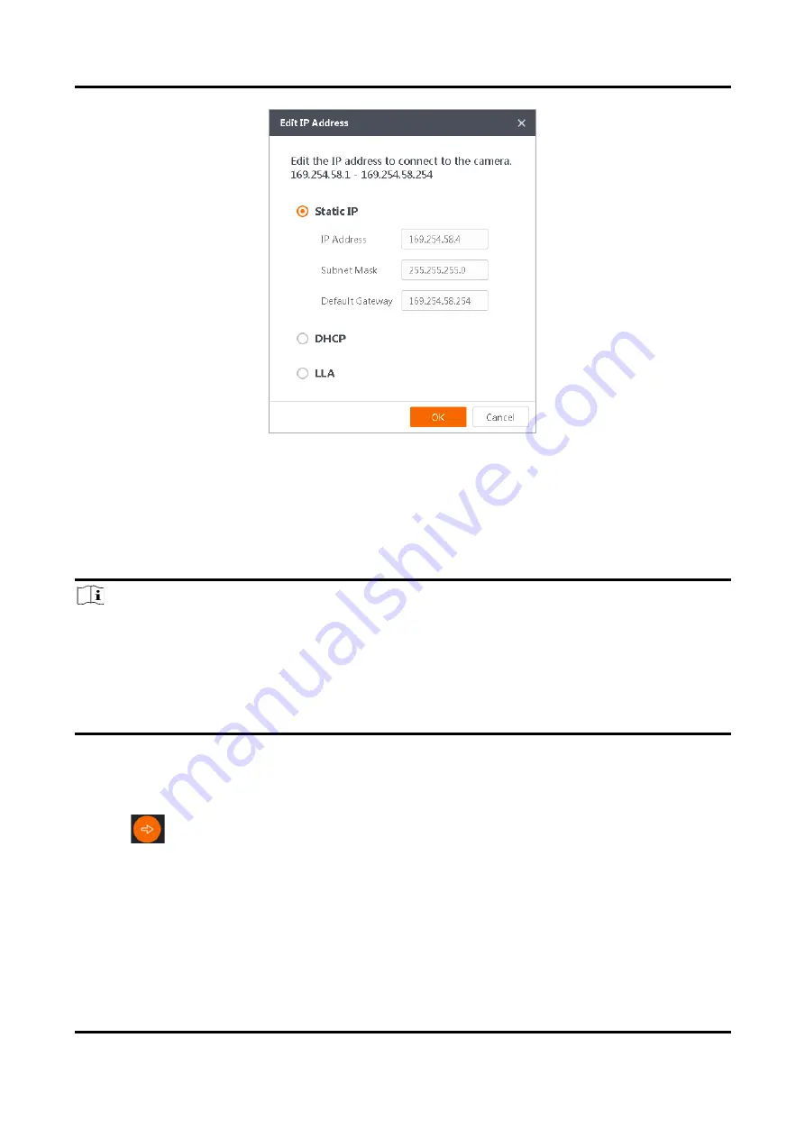
Figure 5-4 Edit IP Address 

6. Click OK. 

5.5 Login 

Note 


Make sure that your device IP address is in the same network segment with the PC where you 
installed the client software before connecting the device to it. 


The default login password is Abc1234, and it is highly recommended to change the password for 
the first time use. 


Follow the guidance to find the password if you forget it. 


Refer to the user manual of the SCMVS client software for detailed operation. 


Steps   
1. Click the device in the device list. 
2. Enter password. 

3. Click 

  to log in. 

Summary of Contents for SC2000E Mini Series

Page 1: ...SC2000E Mini Series Vision Sensor Quick Start Guide ...

Page 2: ...PECIAL CONSEQUENTIAL INCIDENTAL OR INDIRECT DAMAGES INCLUDING AMONG OTHERS DAMAGES FOR LOSS OF BUSINESS PROFITS BUSINESS INTERRUPTION OR LOSS OF DATA CORRUPTION OF SYSTEMS OR LOSS OF DOCUMENTATION WHETHER BASED ON BREACH OF CONTRACT TORT INCLUDING NEGLIGENCE PRODUCT LIABILITY OR OTHERWISE IN CONNECTION WITH THE USE OF THE PRODUCT EVEN IF HIKROBOT HAS BEEN ADVISED OF THE POSSIBILITY OF SUCH DAMAGES...

Page 3: ...this equipment in a residential area is likely to cause harmful interference in which case the user will be required to correct the interference at his own expense Reorient or relocate the receiving antenna Increase the separation between the equipment and receiver Connect the equipment into an outlet on a circuit different from that to which the receiver is connected Consult the dealer or an expe...

Page 4: ...t avoided could result in equipment damage data loss performance degradation or unexpected results Indicates a hazard with a high level of risk which if not avoided will result in death or serious injury Available Model This manual is applicable to the SC2000E Mini Series Vision Sensor Safety Instruction These instructions are intended to ensure that the user can use the product correctly to avoid...

Page 5: ...d to avoid heat accumulation Do not contact the radiator directly to avoid scald Electrostatic Protection Remove all conductive objects such as jewelry watch etc on the product body before touching the product and touch the grounding metal bracket by hand to release the static electricity It is suggested to wear anti static suit to prevent damage to the equipment caused by static electricity When ...

Page 6: ...er for protection Installation Please do not install the product on vibrating surface or places that are vulnerable to impact Personnel Requirement Quality requirements for installation and maintenance personnel qualification certificate or working experience in weak current system installation and maintenance and relevant working experience and qualifications Besides the personnel must possess th...

Page 7: ... Install Client Software 7 5 2 Turn off Firewall 8 5 3 Set PC Network 8 5 4 Set Device Network 9 5 5 Login 10 Chapter 6 Client Layout and Operation Flow 12 6 1 Main Window Introduction 12 6 2 Operation Flow 13 Chapter 7 I O and Serial Port Introduction 14 7 1 Bi Directional Signal 14 7 1 1 Configure as Input Signal 14 7 1 2 Configure as Output Signal 15 7 2 I O Wiring 16 7 2 1 Input Wiring 17 7 2 ...

Page 8: ...ries Vision Sensor Quick Start Guide vii 8 2 Why the image is not smooth in live view 21 8 3 Why the image is very dark 21 8 4 Why there is no image in live view 21 8 5 What can I do if I forget the login password 22 ...

Page 9: ...tomized result text output 1 2 Key Feature Adopts embedded hardware platform for high speed image processing Adopts built in positioning and measurement algorithms to detect object s existence count patterns and spots etc Multiple IO interfaces for input and output signals Multiple indicators for displaying device status Adopts light source to ensure uniform brightness in the illuminated area Supp...

Page 10: ...1 Focus Knob It is used to adjust focal length manually 2 Screw Hole It is used to fix the device to the installation position You should use M2 screw 3 Trigger Button When the device is in trigger mode press the button and the device triggers once 4 SR Cable SR cable connector provides power I O Ethernet and serial port 5 LNK Indicator It is a network status indicator The indicator is flashing gr...

Page 11: ... or loading the solution fails it is red 7 PWR Indicator It is a power indicator The indicator is green when the device operates normally When the device starts or exception occurs it is red 8 Light Source It is the LED light source used to provide light when the device acquires images 9 Sensor It is used to acquire images 10 Aiming Light It helps to indicate the field of view and aim targets ...

Page 12: ...nt power supply positive Red open cable 2 Brown open cable 3 4 RS232_TX RS 232 serial port output DB9 serial port 5 RS232_RX RS 232 serial port input DB9 serial port 6 MDI0 Fast Ethernet signal MDI0 RJ45 connector 7 MDI1 Fast Ethernet signal MDI1 RJ45 connector 8 GPIO2 Line 2 Bi directional I O and it is output by default Blue white open cable 9 10 GPIO3 Line 3 Bi directional I O and it is output ...

Page 13: ...rial port connector that corresponds to 4th and 5th pins of the device s 17 pin interface and a RJ45 connector that corresponds to 6th 7th 14th and 15th pins of the 17 pin interface Caution You cannot use the 12 V power plug of the DB9 serial port connector and power supply open line to power the device at the same time Otherwise damaging to the power supply may occur Figure 3 2 17 Pin Cable Note ...

Page 14: ...ply according to the device power supply and consumption You need to purchase separately 4 Screw Package 1 It refers to the supplied M2 screws that are used to fix the device to the installation position 4 2 Install Device Before You Start Make sure that the device in the package is in good condition and all assembly partsare included Make sure that all related devices are powered off during the i...

Page 15: ...n and remote operations Note Check the Windows version The client software is compatible with 32 64 bit Windows 7 10 You can get the client software installation package from https en hikrobotics com The graphic user interface may differ by different versions of client software you use Steps 1 Double click the installation package to install the client software 2 Select the language 3 Read and che...

Page 16: ...ntrol Panel System and Security Windows Defender Firewall 2 Click Turn Windows Defender Firewall on or off on the left 3 Select Turn off Windows Defender Firewall not recommended Figure 5 2 Windows Defender Firewall 4 Click OK 5 3 Set PC Network To ensure stable image transmission and normal communication between the PC and the device via client software you need to set the PC network before using...

Page 17: ...Adapter 2 Select corresponding network interface card and click Link Speed 3 Set Speed and Duplex as Auto Negotiation or 100 Mbps 5 4 Set Device Network You can set and operate the device in the client software only when the device is in the same network segment with the PC where the client software is installed Steps 1 Double click the client software to run it 2 Click in the device list to find ...

Page 18: ... you installed the client software before connecting the device to it The default login password is Abc1234 and it is highly recommended to change the password for the first time use Follow the guidance to find the password if you forget it Refer to the user manual of the SCMVS client software for detailed operation Steps 1 Click the device in the device list 2 Enter password 3 Click to log in ...

Page 19: ...SC2000E Mini Series Vision Sensor Quick Start Guide 11 Figure 5 5 Login Interface 4 Optional Check Remember me to remember the password if necessary ...

Page 20: ...s after logging in If there is no project the client software will create and run a new project Table 6 1 Main Window Description No Name Description 1 Menu Bar The menu bar includes project I O settings communication settings camera settings and operation management 2 Project Status Display Area This area displays operation results of current projects in real time You can run stop or edit project...

Page 21: ...on information here 6 2 Operation Flow Note Refer to the user manual of the SCMVS client software for detailed parameter settings and operations Click More on the upper right corner of the client software and click User Manual to open it You can follow the overall operation flow below to operate the device via the client software Log into Client Software Create Edit Project Parameters Settings Bas...

Page 22: ...ne I O signal can be configured as trigger By default the I O type of Line 0 is trigger the I O type of Line 1 is used to switch solution and the I O type of Line 2 3 is output 7 1 Bi Directional Signal The device has four bi directional I O Line 0 1 2 3 and you can set them as input signal or output signal according to demands Line 0 1 2 3 GPI GPO VCC Figure 7 1 Internal Circuit of Bi Directional...

Page 23: ...igh VH 2 VDC Input Falling Delay TDF 200 ns Input Rising Delay TDR 1 μs 7 1 2 Configure as Output Signal If the bi directional I O is configured as output signal its output signal polarity is NPN and its logic level and electrical feature are shown below Output Level High Internal Logic Output Level Low TR TDR TDF TF 50 50 50 50 10 10 90 90 Figure 7 3 Output Logic Level When the external voltage i...

Page 24: ...mV 5 VDC 260 mV 12 VDC 500 mV 24 VDC 900 mV 7 2 I O Wiring The device can receive input signals from external devices and output signals to external devices This section introduces how to wire the device s I O Note The input and output signals mentioned in this section are the bi directional I O signal whose I O type is configured as trigger and output correspondingly The pull up and pull down res...

Page 25: ...Cable Used If you use external pull down resistor it is recommended to use 1 KΩ pull down resistor Input Signal Device Power PWR Device Power Ground PNP Device PNP Device Power PNP Power Ground Signal Line VCC GND of PWR and VCC Figure 7 5 Input Signal Connecting to PNP Device External Pull Down Resistor Used NPN Device If the VCC of NPN device is 12 VDC or 24 VDC and the pull up resistor of the s...

Page 26: ...nput Signal Connecting to NPN Device External Pull Up Resistor Used Switch If the input signal is switch and its wiring is shown below Input Signal Device Power PWR Device Power Ground GND of PWR and VCC 3 3 V 0 V Figure 7 8 Input Signal Connecting to Switch 7 2 2 Output Wiring Note Output signal wiring may differ by external device types PNP Device Output Signal Device Power PWR PNP Device PNP Po...

Page 27: ...nd the external pull up resistor is used it is recommended to use 1 KΩ pull up resistor Output Signal Device Power PWR Device Power Ground NPN Device NPN Device Power NPN Power Ground Signal Line VCC GND of PWR and VCC Figure 7 11 Output Signal Connecting to NPN Device External Pull Up Resistor Used 7 3 RS 232 Serial Port The device supports outputting data via RS 232 serial port and you can set s...

Page 28: ...SC2000E Mini Series Vision Sensor Quick Start Guide 20 Table 7 4 Pin Definitions Pin No Name Description 2 TX Transmits data 3 RX Receives data 5 GND Signal ground ...

Page 29: ...n the same network segment 8 2 Why the image is not smooth in live view Reason The network transmission speed is not up to 100 Mbps Solution Check if the network transmission speed is up to 100 Mbps 8 3 Why the image is very dark Reason The brightness of light source is not enough Exposure and gain values are too small Solution Increase the brightness of light source or use brighter lamps Increase...

Page 30: ...mode 8 5 What can I do if I forget the login password Solution Click Forgot Password in the login interface to view the device serial No and mail it to the technical support personnel or call them to get the corresponding resetting file After that import the resetting file and reset the password as the default one ...

Page 31: ...UD24853B ...

Reviews: