background image


X86  Open  Platform 


User  Manual 


Summary of Contents for X86

Page 1: ...X86 Open Platform User Manual ...

Page 2: ...TISFACTORY QUALITY OR FITNESS FOR A PARTICULAR PURPOSE THE USE OF THE PRODUCT BY YOU IS AT YOUR OWN RISK IN NO EVENT WILL HIKROBOT BE LIABLE TO YOU FOR ANY SPECIAL CONSEQUENTIAL INCIDENTAL OR INDIRECT DAMAGES INCLUDING AMONG OTHERS DAMAGES FOR LOSS OF BUSINESS PROFITS BUSINESS INTERRUPTION OR LOSS OF DATA CORRUPTION OF SYSTEMS OR LOSS OF DOCUMENTATION WHETHER BASED ON BREACH OF CONTRACT TORT INCLU...

Page 3: ...sted and found to comply with the limits for a Class A digital device pursuant to part 15 of the FCC Rules These limits are designed to provide reasonable protection against harmful interference in a residential installation This equipment generates uses and can radiate radio frequency energy and if not installed and used in accordance with the instructions may cause harmful interference to radio ...

Page 4: ... www recyclethis info 2006 66 EC battery directive This product contains a battery that cannot be disposed of as unsorted municipal waste in the European Union See the product documentation for specific battery information The battery is marked with this symbol which may include lettering to indicate cadmium Cd lead Pb or mercury Hg For proper recycling return the battery to your supplier or to a ...

Page 5: ...ice may be damaged Avoid sudden collision and pack the device with the accompanied carton and cushioning material or similar package Using Environment In order to reduce the risk of fire or electric shock do not let the device get wet or damp Do not drop objects onto the device and avoid vigorous vibration Keep the device away from magnetic interference Do not use the device in extremely heat extr...

Page 6: ...o that when problems arise the device can be packed with packaging materials and sent to the agent or returned to the manufacturer for processing The company does not bear any liability for accidental damage during transportation caused by non original packaging This device is a precision electronic device no components can be maintained by user do not disassemble the device arbitrarily Cleaning D...

Page 7: ...X86 Open Platform User Manual vii E mail tech_support hikrobotics com Website en hikrobotics com ...

Page 8: ... 3 2 Set Network Interface Card 12 3 3 Set IP Address 14 3 4 Connect Device to MVS 15 Chapter 4 Device Setting 16 4 1 Main Window 16 4 2 Set Parameters 17 Chapter 5 Image Acquisition 19 5 1 Set Frame Rate 19 5 2 Set Trigger Mode 19 5 3 External Trigger Mode 20 5 3 1 Set External Trigger Source 20 5 3 2 Set Software Trigger 21 5 3 3 Set Hardware Trigger 21 5 3 4 Set Counter Trigger 22 5 4 Trigger R...

Page 9: ...Test Pattern 38 8 10 Set White Balance 40 8 11 Set Hue 41 8 12 Set Saturation 41 8 13 Multiple Exposure 42 Chapter 9 Other Functions 43 9 1 Device Control 43 9 2 Set Light Source 44 9 3 Save and Load User Set 44 9 4 Set Indicator 45 9 5 Set Communication Control 47 9 6 Update Firmware 47 9 6 1 Update Firmware via MVS 47 9 6 2 Update Firmware via MvOPCUpgrade 48 Chapter 10 Development Guide 49 10 1...

Page 10: ...X86 Open Platform User Manual x 11 1 Overview 58 11 2 Interface 58 11 3 Indicator 60 11 4 I O Wiring 61 11 5 Update Firmware 62 Chapter 12 Trouble Shooting 63 Chapter 13 Revision History 64 ...

Page 11: ...pen platform with light source and lens cover is shown in Figure 1 2 66 1 2 6 3 0 36 55 1 1 5 4 M 4 4 4 M 4 6 Φ69 1 9 113 2 49 Unit mm Figure 1 2 X86 Open Platform with Light Source and Lens Cover The device has 4 screw holes that are used to fix the device to the mounting bracket It is recommended to use supplied M4 screws to fix the device Otherwise you are recommended to use metric M4 screws an...

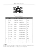
Page 12: ...e designed with screw threads to tighten connection between the device and cables and thus avoid influence caused by vibration 1 2 3 Figure 1 3 Interface Table 1 1 Interface Description No Description 1 Power and I O Interface 2 Expansion interface 3 RJ45 gigabit Ethernet interface 1 3 Power and I O Interface The device has a 12 pin power and I O interface as shown in Figure 1 4 and the respective...

Page 13: ... output 1 Yellow 5 OPTO_OUT2 Output I O isolated output 2 Grey 6 OUT_COM Output Signal output COM Pink 7 OPTO_IN0 Input I O isolated input 0 Blue 8 OPTO_IN1 Input I O isolated input 1 Red 9 OPTO_IN2 Input I O isolated input 2 Black 10 IN_COM Input Signal input COM Purple 11 RS232_R RS232 input Grey pink 12 RS232_T RS232 output Red blue The cable color here refers to the color of cable supplied If ...

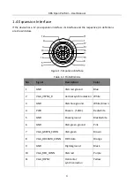
Page 14: ...n Interface Table 1 3 Pin Definitions No Signal Description Color 1 GND VGA red ground Blue 2 VGA_VSYNC_R Vertical synchronization White 3 GND VGA blue ground White brown 4 PWR Power 5 VDC Red white 5 GND Power ground Black white 6 GND VGA green ground Pink 7 VGA_GREEN_CONN VGA green Brown 8 VGA_DDCDATA_CONN DDC data Orange 9 GND Digital ground Black 10 VGA_RED_CONN VGA red Purple 11 VGA_HSYNC Hor...

Page 15: ... 17 The cable color here refers to the color of cable supplied If cable of other manufacturers is used the cable color may differ and the actual cable you purchased shall prevail 1 5 Indicator The device has 5 indicators including power indicator network connection indicator network transmission indicator user indicator 1 and user indicator 2 as shown below PWR LNK ACT U1 U2 Figure 1 6 Indicator ...

Page 16: ...r will display corresponding status Table 1 5 Device Status and Indicator Status Device Status Power Indicator Network Connection Indicator Network Transmission Indicator User Indicator 1 User Indicator 2 Solution Power on Solid blue Solid green Slow or fast yellow flash Unlit Slow blue flash Power exception Unlit Unlit Unlit Unlit Unlit Check power wiring Network exception Solid blue Unlit Unlit ...

Page 17: ...e interface expansion cable 4 Interface expansion module 1 It refers to the interface expansion module 5 DC switching power supply 1 Power adapter above 12 VDC 2 A or 24 VDC 1 A 6 Lens 1 It refers to C mount lens 7 Mounting bracket 1 It is used to fix the device 8 Waterproof lens cover 1 It is used to protect lens and light source 2 2 Install and Change Lens Follow steps below to install or change...

Page 18: ...isassembling lamp cup Figure 2 1 Install Lens Instructions on disassembling lamp cup Press the clip in the arrow direction to disassemble the lamp cup Figure 2 2 Change Lens 2 3 Install Device The figures below show 3 installation methods of the device You can use M4 screws to fix the device to the required position ...

Page 19: ...X86 Open Platform User Manual 9 安装方式一示意图 Figure 2 3 Installation Method 1 安装方式二示意图 Figure 2 4 Installation Method 2 安装方式三示意图 Figure 2 5 Installation Method 3 ...

Page 20: ...he device to a switch or a network interface card NIC Figure 2 6 Connect Network Cable 2 Use 12 pin power and I O cable to connect the device to a proper power adapter or switching power supply Figure 2 7 Connect Power and I O Cable 3 If expansion interface is required connect corresponding cable as shown below Figure 2 8 Connect Expansion Interface Cable ...

Page 21: ...faces of the expansion interface board OUT_COM OUT0 1 2 IN_COM IN0 1 2 Expansion Interface Board 12 pin Power Cable Smart Camera Figure 2 9 Expansion Interface Board Wiring If device s built in light source is not used you can use 10 VDC to 30 VDC for power supply If device s built in light source is used you have to use 20 VDC to 30 VDC for power supply ...

Page 22: ...ions are used the graphic user interface may differ You can download the client software installation package from en hikrobotics com Steps 1 Double click MVS installation package to install the client Figure 3 1 Installation Interface 2 Read the Terms of the License Agreement and check it 3 Click Start Setup 3 2 Set Network Interface Card Steps 1 After installing MVS client click Start Menu of th...

Page 23: ... an IP address automatically and click OK to save Figure 3 3 Local NIC Settings 5 Click Apply to take the settings into effect If you are not sure about the parameter functions you can keep the cursor on the to view the parameter description You can also set the Jumbo Packet and local network in your PC by accessing the NIC settings ...

Page 24: ... the device Only when the device is in the same network segment with the PC can you operate the device via the MVS For MVS below V3 0 0 please turn off the firewall in your PC Steps 1 Run the MVS client software 2 Click Tools IP Configurator to open the IP Configurator 3 Select the device to be modified in the device list 4 Click Modify IP to open the Modify IP Address window Here we take Static I...

Page 25: ... IP address conflicts with another device s IP address in the same local subnet The parameters in the figure are only for reference Please enter the parameters according to the actual situation 3 4 Connect Device to MVS Steps 1 Power on the device 2 Double click the MVS client to open it 3 Click to find the device in device list 4 Double click the device or click to connect it to the client Figure...

Page 26: ...y Figure 4 1 Main Window For specific main window of the MVS client please refer to the actual one you got Table 4 1 Description of the Main Window No Area Name Description 1 Menu Bar Function modules including File View Settings Tool and Help 2 Control Toolbar The control toolbar provides quick operations for images 3 Device List Panel Display current device list and provide icons for connecting ...

Page 27: ...l time image of the device 6 Feature Panel Display and configure the device s specific attributes 4 2 Set Parameters The device setting supports 3 types of user level Beginner Expert and Guru which displays different device attributes For Guru Level it provides the most comprehensive camera attribute for professional use Here we take Guru Level as an example Figure 4 2 Feature Tree ...

Page 28: ...ou can view and set related parameters of supplement light Trigger and IO Control You can view and set device s debugging information Communication Control You can view and set data communication method User Set Control You can save or load the device s parameters set the default parameters when running the software confirm certain information via two user indicators Debug Info You can view device...

Page 29: ...mode including internal trigger mode and external trigger mode The trigger mode principle and parameter setting are shown below Table 5 1 Trigger Mode Principle and Parameter Trigger Mode Parameter Parameter Value Principle Internal trigger mode Trigger and IO Control Trigger Mode Off The camera acquires images via its internal signals External trigger mode Trigger and IO Control Trigger Mode On T...

Page 30: ...igger Mode External Trigger Source Parameter Parameter Value Principle Software trigger Trigger and IO Control Trigger In Source Software The software sends trigger signal to the X86 open platform to acquire images Hardware trigger Trigger and IO Control Trigger In Source LineIn 0 LineIn 1 LineIn 2 External device connects X86 open platform via I O interface External device sends trigger signal to...

Page 31: ...ou can set software trigger as shown below Steps 1 Click Trigger and IO Control Trigger Mode 2 Select On as Trigger Mode 3 Select Software as Trigger In Source and click Execute in Software Trigger In to send trigger commands Figure 5 3 Set Software Trigger 5 3 3 Set Hardware Trigger You can set hardware trigger as shown below Steps 1 Click Trigger and IO Control Trigger Mode ...

Page 32: ...elect On as Trigger Mode 3 Select Counter 0 as Trigger In Source 4 Set Count Number according to actual demands and its range is from 1 to 1023 Figure 5 4 Set Counter Trigger 5 4 Trigger Related Parameters Under hardware trigger you can set trigger polarity burst frame count trigger delay and trigger debouncer 5 4 1 Set Trigger Polarity You can set trigger activation as shown below Steps 1 Click T...

Page 33: ... Sensor exposure Exposure 1 Trigger delay Exposure 2 Exposure 3 Figure 5 5 Sequence Diagram of Burst Frame Count 5 4 3 Set Trigger Delay From the device receiving signal and responding this period is trigger delay Its sequence diagram is shown below Sensor exposure Exposure 1 Exposure 2 Exposure 3 Trigger_in 1 Trigger delay Trigger_in 2 Trigger delay Trigger_in 3 Trigger delay Figure 5 6 Signal De...

Page 34: ... signal bounce that may cause false trigger Thus it is necessary to debounce the external trigger signal and its sequence diagram is shown below Trigger_in1 Trigger_in2 Trigger_in3 Trigger_in2 Trigger_in3 Before debounce After debounce Debouncer Time Debouncer Time Figure 5 9 Trigger Debouncer Sequence Diagram You can set trigger debouncer as shown below Steps 1 Click Trigger and IO Control Debouc...

Page 35: ...X86 Open Platform User Manual 25 Figure 5 10 Set Trigger Debouncer When the configured deboucer time is longer than the trigger signal time this trigger signal will be ignored ...

Page 36: ...You can select output signal as shown below Steps 1 Click Trigger and IO Control Line Out Selector 2 Select LineOut 0 LineOut 1 or LineOut 2 as Line Out Selector according to actual demands Figure 6 1 Select Output Signal 6 2 Set Output Event Steps 1 Click Trigger and IO Control Line Out Activation Event 2 Select different output events as Line Out Activation Event according to actual demands Figu...

Page 37: ...I O edge signal when stopping triggering and acquiring images under Burst mode 6 ExposureStartActive It refers to output one I O edge signal when starting exposure 7 CountActive It refers to output one I O edge signal when counter output is enabled 8 TimerActive It refers to output one I O edge signal when timer output is enabled 9 HardTriggerActive It refers to output one I O edge signal when har...

Page 38: ...X86 Open Platform User Manual 28 Figure 6 3 Set Output Delay Duration or Ahead Time ...

Page 39: ...NPN signal suspended or power negative IN_COM should be connected with input device power positive and signal line with corresponding input interface Signal Line OPTO IN IN _ COM Power Power Ground NPN Signal Ground _ Figure 7 2 Connecting to NPN Device If the input device is PNP signal suspended or power positive IN_COM should be connected with input device power negative and signal line with cor...

Page 40: ...ut as shown below Input voltage ranges from 5 VDC to 30 VDC and current cannot exceed 200 mA Figure 7 4 I O Output Wiring If the output device is NPN signal suspended or power negative OUT_COM should be connected with input device power positive and signal line with corresponding input interface NPN OPTO OUT _ OUT_COM Power Signal Line Power Ground Figure 7 5 Connecting to NPN Device ...

Page 41: ...tive the OUT_COM should be connected with input device power negative and signal line with corresponding input interface PNP OPTO OUT _ OUT_COM Power Signal Line Power Ground Figure 7 6 Connecting to PNP Device Do not directly connect with inductive load e g relay DC motor etc when outputting ...

Page 42: ... Frame Rate displays the device s real time frame rate 8 2 Set ROI If you are only interested in a certain region of the image you can set a Region of Interest ROI for the device Setting ROI can reduce the bandwidth of the image being transmitted Thus increasing the frame rate to some extent Steps 1 Click Image Setting and find Image Width Image Height 2 Enter proper value in Image Width and Image...

Page 43: ...Image Setting Pixel Format 2 Set Pixel Format according to actual demands Figure 8 3 Set Pixel Format 8 4 Set Exposure Mode The X86 open platform supports exposure function For specific exposure range that the device supports please refer to the specifications of the device The device has 3 types of exposure Off Once and Continuous The exposure mode and principle are shown below Table 8 1 Exposure...

Page 44: ...device adjusts the exposure time continuously according to the image brightness You can set exposure mode as shown below Steps 1 Click Image Setting Exposure Auto 2 Set Exposure Auto according to actual demands Figure 8 4 Set Exposure Mode When Exposure Auto is Off you can set exposure time by enter proper value in Exposure Time µs Figure 8 5 Set Exposure Time When the device is under Once or Cont...

Page 45: ...ng Gain Auto Off The device adjusts gain according to the value configured by user in Gain dB Once Image Setting Gain Auto Once The device adjusts the gain automatically according to the image brightness After adjustment it will switch to Off Mode Continuous Image Setting Gain Auto Continuous The device adjusts the gain continuously according to the image brightness You can set gain as shown below...

Page 46: ...djusts exposure time 8 6 Set Gamma Correction The X86 open platform supports Gamma correction function Generally the output of the camera s sensor is linear with the photons that are illuminated on the photosensitive surface of the sensor Gamma correction provides a non linear mapping mechanism as shown below Gamma value between 0 5 and 1 image brightness increases dark area becomes brighter Gamma...

Page 47: ...ghtness Steps 1 Click Image Setting Brightness 2 Enter proper value in Brightness according to actual demand Figure 8 10 Set Brightness Under Once or Continuous exposure mode or Once or Continuous gain the higher the brightness value the brighter the image will be 8 8 Set Image Reverse The X86 open platform supports horizontal reverse image output Horizontal reverse refers to the image reverses in...

Page 48: ...imilar problem to determine the reason You can set test pattern as shown below Steps 1 Click Image Setting Test Pattern 2 Set Test Pattern according to actual demands Figure 8 12 Set Test Pattern The camera offers 5 test patterns including mono bar checkboard oblique mono bar Vertical Stripe and Transver SeStripe as shown below Figure 8 13 Mono Bar Test Pattern Figure 8 14 Checkboard Test Pattern ...

Page 49: ...rm User Manual 39 Figure 8 15 Oblique Mono Bar Test Pattern Figure 8 16 Vertical Stripe Test Pattern Figure 8 17 Transver SeStripe Test Pattern Vertical Stripe and Transver SeStripe are only available for color device ...

Page 50: ...Balance White Auto Off You need to set the R G B value manually between 1 and 4095 1024 means ratio is 1 0 Once Image Setting Balance White Auto Once Automatic white balance once Adjust the white balance for a certain amount of time then stop It implements an algorithm that finds possible gray areas in the Bayer data Continuous Image Setting Balance White Auto Continuous Continuous automatic white...

Page 51: ...al demand and its default value is 128 Figure 8 19 Set Hue 8 12 Set Saturation Saturation function is only available for color device You can set saturation as shown below Steps 1 Click Image Setting Saturation Enable 2 Enable Saturation Enable 3 Enter proper value in Saturation according to actual demands and its default value is 128 Figure 8 20 Set Saturation The higher the saturation value and ...

Page 52: ...e Setting Multiple Exposure Gain Polling Enable 2 Enable Multiple Exposure Gain Polling Enable 3 Enter proper value in four groups of exposure time and gain according to actual demands as shown below Figure 8 21 Multiple Exposure Gain Polling Enable When acquiring images the device will set each image s exposure and gain in turn according to configured these four groups of parameters ...

Page 53: ...e you can view device information edit device name reset device etc Steps 1 Open the client software 2 Go to Device Control and open the list 3 Enter device name in the Device User ID Figure 9 1 Edit Device User ID You can click Execute in Device Rest to reset the device as shown below Figure 9 2 Reset Device ...

Page 54: ...ght source flashing time and ahead time before exposure respectively For models of X86 open platform that do not have light source and lens cover do not support this function 9 3 Save and Load User Set The device supports 4 sets of parameters including 1 default set and 3 custom sets The relation among 4 sets of parameters is shown below Current Parameter User Parameter 1 User Parameter 2 User Par...

Page 55: ...n User Set Load to load parameters to the device Set User Default You can also set default parameter by selecting parameter from drop down list of User Set Default Save the custom parameters setting and select it as the default one otherwise the device adopts the default set every time after it being rebooted 0 stands for the default factory set 1 stands for the user set 1 2 stands for the user se...

Page 56: ...operating 3 System Running When the device is running properly the indicator keeps flashing 4 Be Triggered When trigger signal inputs indicator flashes once 5 Line0 Out When Line0 Out outputs signal indicator flashes once 6 Line1 Out When Line1 Out outputs signal indicator flashes once 7 Line2 Out When Line2 Out outputs signal indicator flashes once 8 Line3 Out Build in Light When Light port outpu...

Page 57: ...g to actual demands Figure 9 7 Set Communication Control 9 6 Update Firmware 9 6 1 Update Firmware via MVS The device supports updating firmware via MVS client Before updating make sure power cable and others are properly connected Please use the firmware package of the corresponding device model for updating Steps 1 Click Tool Firmware Updater to open the update interface 2 Click to select the de...

Page 58: ...tly 9 6 2 Update Firmware via MvOPCUpgrade The device supports updating firmware via the tool of MvOPCUpgrade By default the tool is located in Program Files x86 MVS Development Bin win32 For different Windows versions the tool location directory may differ Please refer to the actual condition Steps 1 Find the tool and double click it 2 Click Search and select the device you want to update 3 Selec...

Page 59: ...e desktop Steps 1 Find the IP address of the platform in the device information panel 2 Use remote desktop tool to connect to the IP address 3 Enter user name and password to enter the platform Default user name is administrator and password is Operation666 Figure 10 1 Enter the Platform via Remote Desktop You are highly recommended to change the password after first login and use remote control a...

Page 60: ...rectory to find the Development folder Figure 10 3 SDK Directory 3 Read the development guide manual and node list learn how to call platform via the sample program and embed your program to use You can contact technical support personnel via e mail tech_support hikrobotics com for help if you have any problem 10 2 3 Use Third Party Software The X86 open platform supports installing Halcon and Lab...

Page 61: ... files mentioned below may differ Please refer to the actual condition Steps 1 Right click MVS icon and select Open file location 2 Go back 2 levels of directory to find the Development folder 3 Go to Samples VC SimpleSamples FlashDemo and find FlashDemo Figure 10 4 Find FlashDemo 4 Obtain flash memory address 5 Write data into flash memory by calling MV_OPC_WriteMemory interface 6 Obtain flash me...

Page 62: ...d find Samples lvproj Figure 10 5 Find Samples lvproj 4 Open Samples lvproj to load MvCameraPatch dll file which is located in MVS Development Samples Labview MvLVLib x86 Figure 10 6 Load MvCameraPatch dll 5 Open Labview software as shown below Figure 10 7 Front Panel Window 6 Click Window Display Flow Diagram to open flow diagram ...

Page 63: ...ctory to open Vls folder to call sub VI program as shown below Figure 10 8 Call VI Program 9 Right click in the blank space of the front panel and set corresponding controller according to actual demands 10 After programing click Open Device to open the device and click Start to obtain stream Figure 10 9 Obtain Stream ...

Page 64: ... PC to connect the platform you can use Halcon software to obtain stream as follows Steps 1 Install Halcon software into your PC 2 Open the software and enter main interface as shown below Figure 10 10 Main Interface 3 Click Asistants in menu bar to select Open Image Acquisition from drop down list Figure 10 11 Select Open Image Acquisition 4 Enter Image Acquisition interface select Source tab and...

Page 65: ...displayed in the right side of Device Figure 10 13 Connect Device 6 You can click Snap to acquire single frame image and click Live to acquire images continuously In Graphics Window you can obtain image information Figure 10 14 Obtain Stream via Halcon Software 7 Select Parameters tab in Image Acquisition interface to set specific image parameters ...

Page 66: ...n file location 2 Go to MVS Development ThirdPartyPlatformAdapter HalconHDevelop and select hAcqMVision dll file according to Halcon version and computer operation system Figure 10 16 Find HAcqMVision dll File 3 Install hAcqMVision dll file into the Halcon software installation directory 4 After installing open Halcon software and enter Image Acquisition interface 5 Select Source tab and select MV...

Page 67: ...X86 Open Platform User Manual 57 Figure 10 17 Select MVision 6 Connect device and obtain images ...

Page 68: ... USB 2 0 interfaces 1 RS232 serial port and 1 RS485 serial port 1 light source controlling port and a 7 in 7 out IO port Figure 11 1 Interface Expansion Module 11 2 Interface The interfaces of interface expansion module are shown below Figure 11 2 Front Side of the Interface Expansion Module Table 11 1 Interfaces on the Front Side of the Module No Interface Name Description 1 Power Switch It switc...

Page 69: ...Device interface It connects X86 open platform Figure 11 3 Back Side of the Interface Expansion Module Table 11 2 Interfaces on the Back Side of the Module No Interface Name Description 1 Input interface It inputs I O signal 2 Output interface It outputs I O signal 3 Input output interface It inputs outputs I O signal 4 USB expansion interface It is the USB expansion interface 5 USB expansion inte...

Page 70: ...icator The interface expansion module supports real time IO monitoring and provides a sufficient number of indicators as shown below Figure 11 4 Indicator Table 11 3 Indicator Description No Indicator Name Description 1 POWER Power indicator 2 IN 1 Input signal 1 indicator 3 IN 2 Input signal 2 indicator 4 IN 3 Input signal 3 indicator 5 IN 4 Input signal 4 indicator ...

Page 71: ...2 OUT 4 Output signal 4 indicator 13 OUT 5 Output signal 5 indicator 14 OUT 6 Output signal 6 indicator 15 OUT 7 Output signal 7 indicator 11 4 I O Wiring The interface expansion module currently only supports 7 in 7 out IO Please refer to the instruction below when wiring I O interface input wiring method is shown below Input voltage ranges from 5 VDC to 30 VDC Expansion Interface Board Smart Cam...

Page 72: ...ng If the output device is NPN signal suspended or power negative OUT_COM should be connected with input device power positive and signal line with corresponding input interface If the output device is PNP signal suspended or power positive the OUT_COM should be connected with input device power negative and signal line with corresponding input interface Do not directly connect with inductive load...

Page 73: ... to Image Setting set Exposure Auto as Once and set Gain Auto as Once 3 Poor live view image quality The network may be fast Ethernet Confirm whether the network transmission speed is 1 Gbps and PC NIC is the gigabit NIC etc Incorrect jumbo frame setting Set jumbo frame as 9 KB or 9014 bytes 4 No image during live view Although trigger mode is enabled there is no trigger signal In client go to Tri...

Page 74: ... Revision Details 1 2 0 0 UD11162B Jul 31 2018 Original version 2 2 0 1 UD15058B Jun 12 2019 Adopt MVS version 3 0 0 Add Section 8 10 Set White Balance Add Section 8 11 Set Hue Add Section 8 12 Set Saturation Add Section 9 6 Update Firmware Add Section 10 2 3 Use Third Party Software Adjust user manual content structure ...

Page 75: ...UD15058B ...

Reviews: