X86 Open Platform
·
User Manual
4
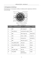
1.4 Expansion Interface
If the device has a 17-pin expansion interface, its interface and the respective pin definitions
are shown below.
1
12
3
7
4
5
6
8
9
10
11
2
13
14
16
15
17
Figure 1-5
Expansion Interface
Table 1-3
Pin Definitions
No.
Signal
Description
Color
1
GND
VGA red ground
Blue
2
VGA_VSYNC_R
Vertical synchronization White
3
GND
VGA blue ground
White/brown
4
PWR
Power + (5 VDC)
Red/white
5
GND
Power ground
Black/white
6
GND
VGA green ground
Pink
7
VGA_GREEN_CONN
VGA green
Brown
8
VGA_DDCDATA_CONN
DDC data
Orange
9
GND
Digital ground
Black
10
VGA_RED_CONN
VGA red
Purple
11
VGA_HSYNC
Horizontal
synchronization
Yellow


