background image

Barrier Gate User Manual 

16 


Table 5-1


Barrier Gate Component Description (1) 

No.  Name 

Quantity 

Barrier gate host 

Boom pole 

Cross recessed pan head screw M3 × 8  1 

Boom pole mounting housing 

Hexagon head bolt M8 × 65 

Flat washer φ 8 

Boom pole mounting cushion block 

Main shaft mounting 

Hexagon check nut M8 

10 

Boom pole mounting housing label 

5.2


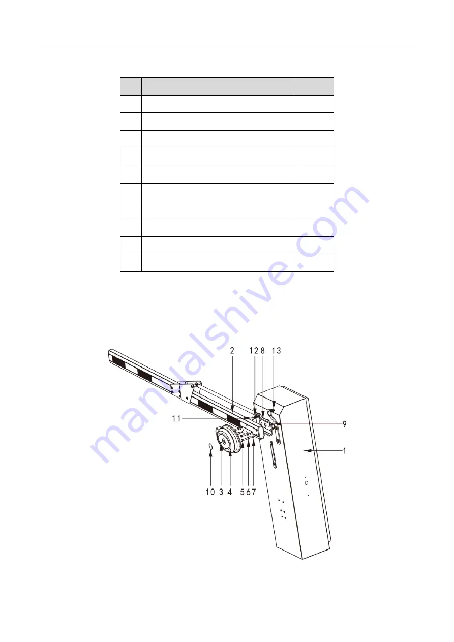
Barrier Gate with Curved Boom Pole 

Refer to the figure and table below for the component description of the barrier gate with curved 
boom pole. 


Figure 5-2


Barrier Gate Component (2) 

Summary of Contents for Barrier gate

Page 1: ...Barrier Gate User Manual ...

Page 2: ...PLICABLE LAW THIS MANUAL AND THE PRODUCT DESCRIBED WITH ITS HARDWARE SOFTWARE AND FIRMWARE ARE PROVIDED AS IS AND WITH ALL FAULTS AND ERRORS HIKVISION MAKES NO WARRANTIES EXPRESS OR IMPLIED INCLUDING WITHOUT LIMITATION MERCHANTABILITY SATISFACTORY QUALITY OR FITNESS FOR A PARTICULAR PURPOSE THE USE OF THE PRODUCT BY YOU IS AT YOUR OWN RISK IN NO EVENT WILL HIKVISION BE LIABLE TO YOU FOR ANY SPECIA...

Page 3: ...CTION OF WEAPONS OF MASS DESTRUCTION THE DEVELOPMENT OR PRODUCTION OF CHEMICAL OR BIOLOGICAL WEAPONS ANY ACTIVITIES IN THE CONTEXT RELATED TO ANY NUCLEAR EXPLOSIVE OR UNSAFE NUCLEAR FUEL CYCLE OR IN SUPPORT OF HUMAN RIGHTS ABUSES IN THE EVENT OF ANY CONFLICTS BETWEEN THIS MANUAL AND THE APPLICABLE LAW THE LATER PREVAILS ...

Page 4: ...2 This device must accept any interference received including interference that may cause undesired operation EU Conformity Statement This product and if applicable the supplied accessories too are marked with CE and comply therefore with the applicable harmonized European standards listed under the EMC Directive 2014 30 EU the LVD Directive 2014 35 EU the RoHS Directive 2011 65 EU 2012 19 EU WEEE...

Page 5: ...ion for detailed power requirements It is recommended to provide independent power adapter for each device as adapter overload may cause over heating or a fire hazard Make sure that the power has been disconnected before you wire install or disassemble the device DO NOT directly touch exposed contacts and components once the device is powered up to avoid electric shock DO NOT use damaged power sup...

Page 6: ...e odor or noise arises from the device immediately turn off the power unplug the power cable and contact the service center If the device is abnormal contact the store you purchased it or the nearest service center DO NOT disassemble or modify the device in any way For the problems caused by unauthorized modification or maintenance the company shall not take any responsibility Keep all wrappers af...

Page 7: ...10 CHAPTER 3 WIRING 13 CHAPTER 4 DIMENSION 14 CHAPTER 5 BARRIER GATE COMPONENT 15 5 1 BARRIER GATE WITH STRAIGHT BOOM POLE 15 5 2 BARRIER GATE WITH CURVED BOOM POLE 16 CHAPTER 6 INSTALLATION 18 6 1 INSTALLATION DESCRIPTION 18 6 2 INSTALLATION 18 6 3 INSTALLATION DEBUG 19 CHAPTER 7 REMOTE CONTROL 20 7 1 BUTTON DESCRIPTION 20 7 1 1 Independent Button 20 7 1 2 Button Combination 20 7 2 DIP SWITCH DES...

Page 8: ...service life of the controller Adopts exact four bar linkage mechanism to keep the boom pole running rapidly and stably and release the motor load to increase the service life Supports manual lock You can rotate the hand wheel on the bottom of motor to control the boom pole manually when the power is cut off 1 2 2 Electrical Feature Highly integrated system connectable to multiple matched devices ...

Page 9: ... pole will fall automatically to guarantee safety Rising signal first When the boom pole is falling if something emergency happens it will rise once receiving the rising signal Rubber strip anti collision The rubber strip on the boom pole can help to decrease damages caused by accident 1 3 Packing List Table 1 1 Packing List No Name Quantity 1 Barrier gate host 1 2 Button switch 1 3 User manual 1 ...

Page 10: ...DO NOT place any object under the boom pole No person is allowed to stand or move under the boom pole when it is falling When the power is cut off shut down the power supply first and then rotate the boom pole to the vertical status with hand wheel The boom pole and the spring have been matched to the best status when the device leaves factory DO NOT increase or decrease the boom pole length or we...

Page 11: ... asynchronous motor The movement is transmitted to the main shaft via four bar linkage mechanism The angle sensor can detect the rotation angle of the output shaft and locate the position of the boom pole accurately Refer to the figure below for the internal structure overview Figure 2 1 Internal Structure 2 2 Machine Core Structure Refer to the figure below for the machine core structure ...

Page 12: ... springs according to the length of the boom pole to reach the moment balance Refer to the table below to select the springs Table 2 1 Spring Description Boom Pole Type Boom Pole Length Range Hole Quantity Spring Quantity and Type Non telescopic straight boom pole L 3 m 1 2 φ 4 5 3 m L 3 5 m 2 2 φ 4 5 3 5 m L 4 2 m 1 2 φ 5 5 4 2 m L 4 7 m 2 2 φ 5 5 4 7 m L 6 m 3 2 φ 5 5 Telescopic straight L 3 m 1...

Page 13: ...m pole Curved boom pole 3 m L 3 5 m 2 2 φ 4 5 3 5 m L 4 m 3 2 φ 4 5 4 m L 5 m 1 2 φ 5 5 5 m L 6 m 2 2 φ 5 5 If the boom pole length changes select the spring type again according to the table above and adjust corresponding parameters ...

Page 14: ...Barrier Gate User Manual 13 Chapter 3 Wiring Refer to the figure below for the wiring of barrier gate Figure 3 1 Wiring ...

Page 15: ...r to the figure below for the dimension of the barrier gate with non telescopic straight boom pole Figure 4 1 Dimension For the barrier gate with telescopic straight boom pole or curved boom pole the dimensions of the host and base are the same as above ...

Page 16: ...l 15 Chapter 5 Barrier Gate Component 5 1 Barrier Gate with Straight Boom Pole Refer to the figure and table below for the component description of the barrier gate with straight boom pole Figure 5 1 Barrier Gate Component 1 ...

Page 17: ...ole mounting housing 1 5 Hexagon head bolt M8 65 4 6 Flat washer φ 8 4 7 Boom pole mounting cushion block 1 8 Main shaft mounting 1 9 Hexagon check nut M8 4 10 Boom pole mounting housing label 1 5 2 Barrier Gate with Curved Boom Pole Refer to the figure and table below for the component description of the barrier gate with curved boom pole Figure 5 2 Barrier Gate Component 2 ...

Page 18: ...le 1 3 Cross recessed pan head screw M3 8 1 4 Boom pole mounting housing 1 5 Hexagon head bolt M8 65 4 6 Flat washer φ 8 4 7 Boom pole mounting cushion block 1 8 Main shaft mounting 1 9 Hexagon check nut M8 4 10 Boom pole mounting housing label 1 11 Hexagon head bolt M10 30 3 12 Flat washer φ 10 5 13 Hexagon check nut M10 1 ...

Page 19: ...t firmly Rotate the crank handle to set the boom pole to the horizontal position to confirm the installation position of the support rod at the end of the boom pole and fix the support rod firmly with screws Ignore this if there is no support rod Connect the power cables and control wires to the control board of the host according to the wiring diagram Fasten them and start debug after confirming ...

Page 20: ...od firmly with screws 4 Install peripheral devices 1 After the barrier gate installation and debug completes wire the lines in the host and connect the control lines of the peripheral devices according to the wiring diagram 2 Debug the devices 6 3 Installation Debug Problem Debug Method The boom pole is not on the horizontal vertical position 1 Unfasten the two screws on the main shaft crank arm a...

Page 21: ...tus Learn Delete Rise In manual learning mode press the buttons to learn rising limit position In auto learning mode press the buttons to get the rising limit position locate the falling limit position and judge the boom pole direction automatically and calculate the running time of the barrier gate When the status indicator is flashing in the frequency of 0 1 s loosen the buttons Learn Delete Fal...

Page 22: ...it will switch to auto learning mode If it is off it will switch to manual learning mode S2 If it is on small angle induction shield function is enabled and the angle is 20 S3 If it is on delayed boom pole falling is enabled and the default delayed time is ten seconds 7 3 Limit Position Learning Mode Description Manual learning mode To locate the rising and falling limit positions manually and acc...

Page 23: ...witch S1 on 2 Learn limit positions automatically 1 Adjust the boom pole to the rising limit position or falling limit position manually 2 Press Learn Delete and Rise buttons or Learn Delete and Fall buttons Then the boom pole will locate the current position as the rising limit position or falling limit position and locate the falling limit position or rising limit position automatically 3 Adjust...

Page 24: ...it position or falling limit position and the mechanical limit position to ensure the motor can run for more than 0 3 s In angle sensor mode if exception occurs and the device needs to learn the limit positions again auto learning must be done firstly ...

Page 25: ...rs of the device are loose or lost once every month Fasten them in time Pour lubricant to the connectors every three months to keep them working smoothly Check the balance springs after running for 30 000 times and adjust the springs balance in time Check if the easily damaged parts are damaged every six months and change them if necessary ...

Page 26: ...Barrier Gate User Manual 25 UD18756B ...

Reviews: