background image

User Manual of DS-7200-ST Series DVR 


104 


C H A P T E R 1 2 

DVR Management


alarm shop

Summary of Contents for DS-7200-ST Series

Page 1: ...DS 7200 ST Series DVR USER MANUAL Version 1 3 0 alarm shop ...

Page 2: ...N THE IMPLIED WARRANTIES OF MERCHANTABILITY AND FITNESS FOR A PARTICULAR PURPOSE REGARDING THE HIKVISION SOFTWARE HIKVISION DOES NOT WARRANT GUARANTEE OR MAKE ANY REPRESENTATIONS REGARDING THE USE OR THE RESULTS OF THE USE OF THE HIKVISION SOFTWARE IN TERMS OF ITS CORRECTNESS ACCURACY RELIABILITY CURRENTNESS OR OTHERWISE THE ENTIRE RISK AS TO THE RESULTS AND PERFORMANCE OF THE HIKVISION SOFTWARE I...

Page 3: ...nsorted municipal waste in the European Union For proper recycling return this product to your local supplier upon the purchase of equivalent new equipment or dispose of it at designated collection points For more information see www recyclethis info 2006 66 EC battery directive This product contains a battery that cannot be disposed of as unsorted municipal waste in the European Union See the pro...

Page 4: ...nding Earthing To avoid shock ensure that all AC wiring is not exposed and that the earth grounding is maintained Ensure that any equipment to which this device will be attached is also connected to properly wired grounded receptacles and are approved medical devices Power Connect and Disconnect The AC power supply cord is the main disconnect device to mains AC power The socket outlet shall be ins...

Page 5: ...y be hot care should be taken to avoid contact with these components Electro Magnetic Interference This equipment has not been tested for compliance with emissions limits of FCC and similar international regulations This device is not and may not be offered for sale or lease or sold or leased until authorization from the United States FCC or its equivalent in other countries has been obtained Use ...

Page 6: ...ST SE DS 7216HFI ST SE DS 7204HVI ST SN DS 7208HVI ST SN DS 7216HVI ST SN DS 7204HFI ST SN DS 7208HFI ST SN DS 7216HFI ST SN DS 7204HVI ST RW DS 7208HVI ST RW DS 7216HVI ST RW DS 7204HFI ST RW DS 7208HFI ST RW DS 7216HFI ST RW and DS 7204HVI ST L series DVR This manual may contain several technically incorrect places or printing errors and the content is subject to change without notice The update...

Page 7: ...rly secured to a rack or shelf Major shocks or jolts to the unit as a result of dropping it may cause damage to the sensitive electronics within the unit Use the DVR in conjunction with an UPS if possible Power down the unit before connecting and disconnecting accessories and peripherals A factory recommended HDD should be used for this device Improper use or replacement of the battery may result ...

Page 8: ... Configuring Record Settings 48 Before Record Settings 48 Initializing Record Settings 48 Scheduling Recording 49 Starting a Manual Recording 50 Protecting Recorded Files 51 Locking Unlocking Recorded Files 51 Setting HDD to Read Only 52 Configuring Advanced HDD Settings 53 Setting up HDD Redundancy 53 C H A P T E R 5 55 Playback 55 Video Playback 56 Playing back by Channel 56 Playing back by Vide...

Page 9: ... Customize Patterns 93 C H A P T E R 1 0 94 Camera Management 94 OSD Settings 95 Video Input Output Mode Settings 95 Image Settings 96 Privacy Mask Settings 97 C H A P T E R 1 1 98 HDD Management 98 Managing HDDs 99 Initializing HDDs 99 Setting HDD Groups 99 Setting HDD Status 100 Checking HDD Status 101 Configuring HDD Alarms 103 C H A P T E R 1 2 104 DVR Management 104 Configuring System Setting...

Page 10: ...User Manual of DS 7200 ST Series DVR 9 C H A P T E R 1 Introduction alarm shop ...

Page 11: ...ideo surveillance product as well as to build up a powerful surveillance network making it is perfect for home or small business applications Figure 1 DS 7204HVI ST DS 7204HVI ST SE DS 7204HFI ST DS 7204HFI ST SE Series DVR Figure 2 DS 7208HVI ST DS 7208HVI ST SE DS 7208HFI ST DS 7216HFI ST DS 7208HFI ST SE DS 7216HFI ST SE Series DVR Figure 3 DS 7216HVI ST DS 7216HVI ST SE Series DVR Figure 4 DS ...

Page 12: ...iew mode Shield of assigned channel for live view Privacy masking capability Multiple PTZ protocols supported and settings and callup of presets patrols and patterns Video image zoom in by clicking the mouse and tracing by dragging mouse in PTZ control mode Hard Disk Management Connection to 1 SATA hard disk for DS 7204HVI ST DS 7204HVI ST SE DS 7208HVI ST SE DS 7200HVI ST SN DS 7204HFI ST DS 7204...

Page 13: ...00HVI ST SN and DS 7200HFI ST SN models provide no alarm in out DS 7204HVI ST SE and DS 7204HVI ST SN models do not support sending Email with attached alarm images Others Control of DVR via mouse and IR remote control Three level user management each user with individual operating permission for DVR and camera Powerful record and search for log of operation alarm and exceptions Import export of d...

Page 14: ...uct Application Diagram Figure 8 Product Application Diagram Operating Your DVR There are numerous ways to navigate and operate your DVR You may use the Front Panel Controls the included IR Infrared Remote a Mouse and the Soft Keyboard alarm shop ...

Page 15: ... 3 Playback for direct access to playback interface 7PQRS REC 1 Enter numeral 7 2 Enter letters PQRS 3 Manual record for direct access to manual record interface manually enable disable record 8TUV PTZ 1 Enter numeral 8 2 Enter letters TUV 3 Access PTZ control interface 9WXYZ PREV 1 Enter numeral 9 2 Enter letters WXYZ 3 Multi camera display in live view 0 A 1 Enter numeral 0 2 switch between inpu...

Page 16: ... numeral 5 2 Enter letters JKL 3 Delete characters before cursor 4 Select the checkbox and ON OFF switch 5 Start stop record clipping in playback 6MNO PLAY 1 Enter numeral 6 2 Enter letters MNO 3 Playback for direct access to playback interface 7PQRS REC 1 Enter numeral 7 2 Enter letters PQRS 3 Manual record for direct access to manual record interface manually enable disable record 8TUV PTZ 1 Ent...

Page 17: ...quence 6 SHIFT Switch of compound keys between the numeric letter input and functional control 7 Compound Buttons 1 MENU 1 Enter numeral 1 2 Access the main menu interface 2ABC F1 1 Enter numeral 2 2 Enter letters ABC 3 The F1 button when used in a list field will select all items on the list In PTZ Control mode it will turn on off PTZ light 3DEF F2 1 Enter numeral 3 2 Enter letters DEF 3 The F2 b...

Page 18: ...etwork connection is functioning normally 2 IR Receiver operation by IR remote control 3 USB Interface Connects USB mouse or USB flash memory devices DS 7216HFI ST SN Figure 13 DS 7216HFI ST SN Front Panel 1 Status Indicators POWER the POWER indicator turns green when DVR is powered up STATUS the indicator lights when the compound key switches to numeric letter input mode Tx Rx TX RX indictor flic...

Page 19: ...ter letters MNO 3 Playback for direct access to playback interface 7PQRS REC 1 Enter numeral 7 2 Enter letters PQRS 3 Manual record for direct access to manual record interface manually enable disable record 8TUV PTZ 1 Enter numeral 8 2 Enter letters TUV 3 Access PTZ control interface 9WXYZ PREV 1 Enter numeral 9 2 Enter letters WXYZ 3 Multi camera display in live view 0 A 1 Enter numeral 0 2 swit...

Page 20: ...ttons 1 MENU 1 Enter numeral 1 2 Access the main menu interface 2ABC F1 1 Enter numeral 2 2 Enter letters ABC 3 The F1 button when used in a list field will select all items on the list In PTZ Control mode it will turn on off PTZ light 3DEF F2 1 Enter numeral 3 2 Enter letters DEF 3 The F2 button is used to cycle through tab pages It will also bring up the Channel OSD Position settings 4GHI ESC 1 ...

Page 21: ... 12 DIRECTION ENTER Buttons Same as DIRECTION ENTER buttons on front panel 13 PTZ Same as 8TUV PTZ button on front panel 14 ESC Same as ESC button on front panel 15 RESERVED Reserved 16 F1 Same as 2ABC button on front panel 17 PTZ CONTROL Buttons Buttons to adjust the iris focus and zoom of a PTZ camera 18 F2 Button The F2 button is used to cycle through tab pages It can also be used to enter the ...

Page 22: ...uble Click Switch between single screen and multi screen mode in Live View Playback mode Click and Drag Clicking and dragging the Left mouse button can be used to control the pan tilt of a PTZ camera as well as to vary the position of digital zoom area and camera OSD It can also be used to setup the alarm areas 2 Right Button Single Click Shows pop up menu 3 Scroll Wheel Scroll Up In Live View mod...

Page 23: ...ut 3 AUDIO IN RCA connectors for analog audio input 4 LINE IN RCA connector for audio input 5 AUDIO OUT RCA connector for audio output 6 LAN Connector for LAN Local Area Network 7 VGA DB15 connector for VGA output Display local video output and menu 8 USB Connector for USB devices 9 RS 232 Interface DB9 connector for RS 232 devices 10 ALARM IN Connector for alarm input ALARM OUT Connector for alar...

Page 24: ...INE IN RCA connector for audio input 5 AUDIO OUT RCA connector for audio output 6 VGA DB15 connector for VGA output Display local video output and menu 7 RS 232 Interface DB9 connector for RS 232 devices 8 LAN Connector for LAN Local Area Network 9 USB Connector for USB devices 10 RS 485 Interface Connector for RS 485 devices T T pin connects to PTZ 11 ALARM IN Connector for alarm input ALARM OUT ...

Page 25: ...tors for video output 3 VIDEO IN BNC connectors for analog video input 4 AUDIO IN RCA connectors for analog audio input AUDIO OUT RCA connector for audio output 5 VGA DB15 connector for VGA output Display local video output and menu 6 LAN Connector for LAN Local Area Network 7 RS 485 Interface Connector for RS 485 devices T T pin connects to PTZ 8 12V 12VDC power supply 9 POWER Switch for turn on ...

Page 26: ...ors for video output 3 VIDEO IN BNC connectors for analog video input 4 AUDIO IN RCA connectors for analog audio input 5 AUDIO OUT RCA connector for audio output 6 VGA DB15 connector for VGA output Display local video output and menu 7 LAN Connector for LAN Local Area Network 8 RS 485 Interface Connector for RS 485 devices D D pin connects to PTZ 9 12V 12VDC power supply 10 POWER Switch for turn o...

Page 27: ...put 5 AUDIO OUT RCA connector for audio output 6 LAN Connector for LAN Local Area Network 7 VGA DB15 connector for VGA output Display local video output and menu 8 USB Connector for USB devices 9 RS 232 Interface DB9 connector for RS 232 devices 10 ALARM IN Connector for alarm input ALARM OUT Connector for alarm output RS 485 Interface Connector for RS 485 devices T T pin connects to PTZ 11 12V 12...

Page 28: ...ut 4 LINE IN RCA connector for audio input 5 AUDIO OUT RCA connector for audio output 6 VGA DB15 connector for VGA output Display local video output and menu 7 RS 232 Interface DB9 connector for RS 232 devices 8 LAN Connector for LAN Local Area Network 9 USB Connector for USB devices 10 RS 485 Interface Connector for RS 485 devices T T pin connects to PTZ 11 ALARM IN Connector for alarm input ALAR...

Page 29: ...A connector for audio output 6 LAN Connector for LAN Local Area Network 7 VGA DB15 connector for VGA output Display local video output and menu 8 USB Connector for USB devices 9 RS 232 Interface DB9 connector for RS232 devices 10 ALARM IN Connector for alarm input ALARM OUT Connector for alarm output RS 485 Interface Connector for RS 485 devices T T pin connects to PTZ 11 POWER Switch for turn on ...

Page 30: ...INE IN RCA connector for audio input 5 AUDIO OUT RCA connector for audio output 6 RS 232 Interface DB9 connector for RS 232 devices 7 VGA DB15 connector for VGA output Display local video output and menu 8 LAN Connector for LAN Local Area Network 9 USB Connector for USB devices 10 RS 485 Interface Connector for RS 485 devices T T pin connects to PTZ 11 ALARM IN Connector for alarm input ALARM OUT ...

Page 31: ...tors for video output 3 VIDEO IN BNC connectors for analog video input 4 AUDIO IN RCA connectors for analog audio input AUDIO OUT RCA connector for audio output 5 VGA DB15 connector for VGA output Display local video output and menu 6 LAN Connector for LAN Local Area Network 7 RS 485 Interface Connector for RS 485 devices T T pin connects to PTZ 8 12V 12VDC power supply 9 POWER Switch for turn on ...

Page 32: ...ors for video output 3 VIDEO IN BNC connectors for analog video input 4 AUDIO IN RCA connectors for analog audio input 5 AUDIO OUT RCA connector for audio output 6 VGA DB15 connector for VGA output Display local video output and menu 7 LAN Connector for LAN Local Area Network 8 RS 485 Interface Connector for RS 485 devices D D pin connects to PTZ 9 12V 12VDC power supply 10 POWER Switch for turn o...

Page 33: ...put 5 AUDIO OUT RCA connector for audio output 6 LAN Connector for LAN Local Area Network 7 VGA DB15 connector for VGA output Display local video output and menu 8 USB Connector for USB devices 9 RS 232 Interface DB9 connector for RS 232 devices 10 ALARM IN Connector for alarm input ALARM OUT Connector for alarm output RS 485 Interface Connector for RS 485 devices T T pin connects to PTZ 11 12V 12...

Page 34: ...ut 4 LINE IN RCA connector for audio input 5 AUDIO OUT RCA connector for audio output 6 VGA DB15 connector for VGA output Display local video output and menu 7 RS 232 Interface DB9 connector for RS 232 devices 8 LAN Connector for LAN Local Area Network 9 USB Connector for USB devices 10 RS 485 Interface Connector for RS 485 devices T T pin connects to PTZ 11 ALARM IN Connector for alarm input ALAR...

Page 35: ...N RCA connector for audio input AUDIO OUT RCA connector for audio output 5 LAN Connector for LAN Local Area Network 6 USB Connector for USB devices 7 ALARM IN Connector for alarm input ALARM OUT Connector for alarm output RS 485 Interface Connector for RS 485 devices T T pin connects to PTZ 8 VGA DB15 connector for VGA output Display local video output and menu 9 RS 232 Interface DB9 connector for...

Page 36: ...User Manual of DS 7200 ST Series DVR 35 C H A P T E R 2 Getting Started alarm shop ...

Page 37: ...he POWER indicator will light green and the startup window will appear To shut down the DVR 1 Enter the Shut Down menu shown in Figure 1 by clicking on Menu ShutDown Figure 1 Shutdown Menu 2 Select the ShutDown button 3 Click the Yes button in the pop up attention box to confirm the shutdown 4 For the DS 7200HVI ST SN and DS 7200HFI ST SN models you are allowed to power off the unit only when the ...

Page 38: ...time until the factory default settings are resumed and if you select the checkbox as the device will automatically access the Setup Wizard dialog box when it starts up next time Figure 3 Setup Wizard To start using the Setup Wizard 1 Click the Next button on the Wizard window This will take you to the User Permission window shown in Figure 4 Figure 4 User Permission 2 Navigate to the Admin Passwo...

Page 39: ...nitialized click the OK button which will take you back to the Setup Wizard window 9 Click Next button to enter the Record Settings dialogue box as shown in Figure 6 Figure 6 Record Settings 10 Click the Enter button to enter Record Settings interface 11 Select the Schedule tab shown in Figure 7 Figure 7 Schedule Settings 12 Click Edit button to enter a new recording schedule shown in Figure 8 13 ...

Page 40: ...rk Settings 16 To configure network settings click the Enter button 17 Enter the IP Address Subnet Mask and Default Gateway settings 18 Click OK button to return to the Setup Wizard 19 If all the settings have been entered click Done to finish the Setup Wizard 20 If you have not initialized or formatted the HDD the following prompt will pop up to remind you to initialize the HDD You can click the ...

Page 41: ...w by clicking the MENU button on the remote or front panel You can also go to the Menu window by right clicking with the mouse and clicking the Menu button 2 Click the Settings icon 3 Click the General icon You will be taken to the General Settings window as shown in Figure 11 Figure 11 General Settings 4 Enter the correct date and time in System Time 5 Click the Apply button to save the setting a...

Page 42: ...User Manual of DS 7200 ST Series DVR 41 C H A P T E R 3 Live View alarm shop ...

Page 43: ...or triggered from motion or alarm Event Alarm Record Figure 1 Live View Icons Note Status for video loss alarm is only valid with analog cameras Live View Operation In Live View mode you can operate the following functions 1 Display Single Camera By Front Panel Remote Use Alphanumeric buttons By Mouse Select Single Camera in right click menu 2 Multi camera Live View By Front Panel Remote Press PRE...

Page 44: ...ing less than the maximum number of cameras in Live View select this option to switch to the next camera display Start Auto switch Enable multi camera sequence in Live View mode Manual Record Enter Manual Record menu to enable camera s to start recording Playback Enter Playback mode of the selected camera Video Search Search the video files PTZ Enter PTZ Control mode of the selected camera Digital...

Page 45: ...e See Setting Camera Order Enable Audio Output Enable disable audio output for the selected video output Event Output Select the port for event output to VGA or Main CVBS Event Dwell Time Set the dwell time for event video display Notes 1 You can select the Main Monitor or Aux Monitor from the right click menu in live view mode 2 DS 7200 ST will automatically detect whether this is VGA display con...

Page 46: ... button on the front panel to switch the camera display 5 The connection or disconnection of VGA display in the process of device running will not affect its functions as shown above Setting Camera Order The Camera Order settings allow you to set camera sequence in selectable live view display mode See the following figure Figure 5 Camera Order Settings Operate the following steps to set camera or...

Page 47: ...ation Live View to enter the Live View Settings interface 2 Select the Channel Zero Encoding tab Figure 6 Channel Zero Encoding 3 Check the checkbox after Enable Channel Zero Encoding 4 Configure the Frame Rate and Max Bitrate The video source of channel zero is from video Main CVBS output and you are allowed to configure the video divisions camera order and dwell time for channel zero Notes 1 The...

Page 48: ...User Manual of DS 7200 ST Series DVR 47 C H A P T E R 4 Record Settings alarm shop ...

Page 49: ... to Initializing HDD for specific instructions for initializing HDD Initializing Record Settings 1 Click Menu Settings Record to access the Record Settings dialog box shown in Figure 1 Figure 1 General Record Settings 2 Select the camera you want to configure 3 Configure the following settings Encoding Parameters Set the encoding parameters to be Normal or Event Stream Type Set the stream type to ...

Page 50: ...t a HDD to Redundancy property to realize redundant recording Record Audio Enable or disable audio record of the selected camera Click OK to finish settings and return to the previous menu 5 Press the 3DEF F2 button on DVR front panel to select the Advanced tab to access the Advanced Settings submenu shown in Figure 3 6 Enable or disable the Overwrite setting Enabling the Overwrite setting will ca...

Page 51: ...tings about motion detection and alarm recordings please refer to the Configuring Alarms 9 Click the OK button to finish configuration 10 Repeat Steps 3 9 for other cameras or copy settings from one schedule to the others under the Copy To item 11 Click OK to finish configuration and save the schedule settings Note DS 7200HVI ST SE DS 7200HFI ST SE DS 7200HVI ST SN and DS 7200HFI ST SN models prov...

Page 52: ...rch to enter the Video Search dialog box shown in Figure 6 Figure 6 Video Search Menu 2 Search for desired recording by entering search parameters Search parameters include Camera ID Video File Type and Start End Time 3 Click the Search button A list of record files see Figure 7 matching the search parameters will be displayed Figure 7 Video Search Result List 4 Select the file you want to lock un...

Page 53: ...s dialog box shown in Figure 9 Figure 9 HDD Property Settings Menu 5 Set HDD Status to Read only and then click OK to finish the settings Notes 1 Once set to read only the HDD cannot be written to until it is set back to read write R W 2 DS 7204HVI ST DS 7204HVI ST SE DS 7208HVI ST SE DS 7204HFI ST DS 7204HFI ST SE DS 7200HVI ST SN DS 7200HFI ST SN and DS 7204HVI ST L models can be installed with ...

Page 54: ...o be used for redundancy as shown in Figure 10 Figure 10 HDD Management Menu 4 Click the Set button This will take you to the HDD Settings menu 5 Set HDD Status to Redundancy shown in Figure 11 Verify at least one other HDD is set to R W read write 6 Click the OK button to save settings and return to the previous menu Figure 11 HDD Settings 7 Navigate to the Record Settings menu by clicking Menu S...

Page 55: ... 7200 ST Series DVR 54 Figure 12 Additional Record Settings 11 Set Redundantly Record to Yes 12 Click the OK button to save settings 13 Repeat steps 8 12 for other cameras you would like to redundantly record alarm shop ...

Page 56: ...User Manual of DS 7200 ST Series DVR 55 C H A P T E R 5 Playback alarm shop ...

Page 57: ...buttons for video playback Audio On Off Start Stop Clipping Previous File Day 30s backward Pause Stop 30s forward Fast Forwrd Slow Forwrd Next File Day Quit Playback Hide Control Panel Time Line Record Type Line Play Reverse Hide Chanel Status Bar Figure 2 Playback Control Panel Note A blue bar refers to the Normal recording scheduled manual while the red bar indicates Event recording Playing back...

Page 58: ...a 4 After search results are presented select the file you want to play back and click Play Figure 4 Search Results 5 The selected video files will automatically be played in the Playback interface as shown in Figure 5 Figure 5 Playback Interface Multi channel Playback For multi channel playback mode you can select multiple channels for search and click the Play button on the Video Search menu as ...

Page 59: ...recorded by event type e g motion detection 1 Click Menu Event Search to enter the Advanced menu 2 Select the event type to search and set the start end time as shown in Figure 7 Figure 7 Video Event Search Menu 3 Click Search to start searching the video files and the searching results will be listed Figure 8 Search Results alarm shop ...

Page 60: ...igure 10 Event Detail Menu Playing back in Live View Mode To play back recorded files by channel in Live View mode By Using a Mouse 1 Right click the mouse on desired channel and select the Playback option 2 The recorded video files from the selected channel will start playing back in the Playback window An Attention message will appear if there are no recordings found in the previous 5 minutes 3 ...

Page 61: ... want to have simultaneous playback 2 Click to stop the ongoing video playback 3 Click to start multi camera simultaneous playback Notes 1 Up to 16 cameras can be played back simultaneously 2 The camera list operation is accessible by mouse only Please do not operate by front panel 3 If the camera numbered the lowest among the multiple cameras selected for simultaneous playback provides no record ...

Page 62: ...frame in the Playback interface By Using a Mouse 1 Click the Slow Forward button on the Playback Control Panel until the speed changes to Single frame 2 Click the Pause button to advance the video frame by frame By Using the Front Panel Remote Control 1 Press the Down button to select the playback speed to Single frame 2 Press the Enter button to advance the video frame by frame Digital Zoom To us...

Page 63: ...User Manual of DS 7200 ST Series DVR 62 Figure 14 Digital Zoom in Playback Mode alarm shop ...

Page 64: ...User Manual of DS 7200 ST Series DVR 63 C H A P T E R 6 Backup alarm shop ...

Page 65: ...igure 1 Video Search Menu 2 Select desired parameters to search for files to export 3 On the toolbar press the Export button to enter the Record Backup interface with the list of video search results 4 Select the files to export as shown in Figure 2 You may also click the Play button to confirm the record file you want to export Figure 2 Record Backup Menu 5 The size of the currently selected file...

Page 66: ...ce Check for compatibility from vendor 7 Click Start to begin backup process shown in Figure 4 Figure 4 Backup Progress 8 After the backup process has completed Figure 5 you may select the files from your device and click the Play button to verify that it has been exported successfully Figure 5 Export Successful Screen Note Video Player software will automatically be copied on to the device that t...

Page 67: ... export You may also click the Play icon to verify that these files are indeed the ones you would like to export 5 Press the Export button to enter Export menu then you can export the files following the step 6 to step 8 in Chapter Exporting Record Files by Video Search Exporting Video Clips You may also select video clips to export directly in Playback status A maximum of 30 clips can be selected...

Page 68: ...peat for additional clips 5 Press the ESC button to exit from the Playback interface You ll then be prompted to save the clips as shown in Figure 6 6 Click the Yes button to enter Backup interface or select No to exit Playback interface 7 At the Backup interface select the Start button to begin the Backup process Managing Backup Devices To manage backup devices you must first be in the Export menu...

Page 69: ...User Manual of DS 7200 ST Series DVR 68 C H A P T E R 7 Alarm Settings alarm shop ...

Page 70: ...ngs menu shown in Figure 2 Figure 2 Advanced Camera Settings 3 Select Motion Detection first and click the Area Settings button to enter the Motion Detection Area and Sensitivity settings interface 4 As shown in Figure 3 the Motion Detection area allows you to mask areas you want to configure motion detection The maximum area can be set to be full screen You can left click mouse hold and drag it t...

Page 71: ...ect the Exit from the menu to return to the Advanced Camera Settings menu 8 Click the Handle button to enter the Exception Handle menu shown in Figure 5 Figure 5 Triggered Camera Settings 9 Select cameras to trigger for recording when motion is detected by checking the checkboxes under the desired cameras 10 Select the Schedule tab Set the schedule you want motion detection to be enabled Schedule ...

Page 72: ... when motion is detected See Scheduling Recording Note The Trigger Alarm Output option is not available for DS 7200HVI ST SE DS 7200HFI ST SE DS 7200HVI ST SN and DS 7200HFI ST SN models as they provide no alarm in out Sensor Alarm Settings Note This section is invalid for DS 7200HVI ST SE DS 7200HFI ST SE DS 7200HVI ST SN and DS 7200HFI ST SN models as they provide no alarm in out Recordings can ...

Page 73: ...ment Settings 3 Set the alarm input type to be Normally Opened N O or Normally Closed N C 4 Check the checkbox next to Setting and click the Handle button to enter the Alarm Input Handle menu 5 Select the Triggered Camera tab 6 Select cameras to trigger for recording when alarm occurs by checking the checkboxes under the desired cameras as shown in Figure 10 Figure 10 Triggered Cameras Menu alarm ...

Page 74: ...n Figure 11 Figure 11 Alarm Output Interface 2 Select the output you would like to configure and click the Set button This will bring up the settings page for the selected channel Figure 12 Figure 12 Alarm Output Settings 3 Configure the settings for selected output 4 Select OK to save and exit Note If the Hold For option is selected as Manually Stop the alarm will only stop when you manually stop...

Page 75: ...r all alarm outputs at once Clear All Stop all alarm outputs at once 3 Select OK to return to the previous menu Video Loss Detection Your DVR can be set up to detect video loss and trigger an action To set up video loss detection 1 Click Menu Settings Camera to enter Camera Settings menu shown in Figure 14 Figure 14 Camera Management Menu 2 Select the Advanced tab 3 Select the camera to be configu...

Page 76: ... with up to 8 time periods per day Note After having configured the schedule the DVR must be restarted for the new settings to take effect Figure 16 Schedule Settings for Video Loss Detection 7 Select the Handle tab to configure exceptions handling Exception trigger options will be described in the next section See Understanding Exception Trigger Options Figure 17 Exception Handle Menu 8 Click OK ...

Page 77: ... Menu Settings Camera to enter the Camera Settings menu shown in Figure 18 Figure 18 Camera Management Menu 2 Select the Advanced tab 3 Select the camera to be configured with video tampering detection 4 Check the Tamper Detection checkbox to enable this feature as shown in Figure 19 Figure 17 Camera Settings Menu 5 Click the Handle button to enter the Exception Handle menu shown in Figure19 6 Sel...

Page 78: ... Settings The exception setting allows the DVR to alert you when irregular events occur These events include HDD Full All installed HDD are full HDD Error Errors occurred during writing of the HDD no HDD installed or HDD had failed to initialize Network Disconnected Disconnected network cable IP Conflict Conflict in IP address setting Illegal Login Incorrect user ID or password used Video Output S...

Page 79: ...gured under the Popup Alarm Image handle method For alarms that are triggered simultaneously images will be displayed one at a time every 10 seconds default dwell time A different dwell time can be set by going to Menu Settings Display Dwell Time Once the alarm stops cycling of the images will also stop and you ll be returned to the Live View screen Audio Warning Trigger an audible beep when excep...

Page 80: ...User Manual of DS 7200 ST Series DVR 79 C H A P T E R 8 Network Settings alarm shop ...

Page 81: ... DVR to automatically obtain an IP address and other network settings from that server check the DHCP checkbox You may check the DHCP status by going to the Network Status tab as shown in Figure 2 Figure 2 Network Status 4 If you want to configure your own settings enter the settings for IP Address IP address you would like to use for your DVR Subnet Mask Subnet Mask of network Default Gateway IP ...

Page 82: ...cess 1 Click Menu Settings Network to enter the Network Settings menu 2 Select the General tab as shown in Figure 3 Figure 3 Network Settings Menu 3 Select the Advanced tab to enter the Advanced Network Settings menu shown in Figure 4 Figure 4 Advanced Network Settings 4 Click the Set button beside PPPOE to enter PPPoE Settings menu shown in Figure 5 alarm shop ...

Page 83: ... status of your PPPoE connection go to Menu Settings Network and select the Network Status tab Configuring DDNS If your DVR is setup to use PPPoE as its default network connection you may set up Dynamic DNS DDNS to be used in connection To set up DDNS 1 Click Menu Settings Network to enter the Network Settings menu 2 Select the Advanced tab 3 Click the Set button beside DDNS to enter the DDNS sett...

Page 84: ...rver Address for DynDNS e g members dyndns org 2 In the Device Domain Name text field enter the domain obtained from the DynDNS website 3 Enter the User Name and Password registered in the DynDNS website Figure 8 DynDNS Settings easyDDNS Enter default Server Address www hik online com and the DVR Domain Name shown in Figure9 Figure 9 easyDDNS Settings NO IP alarm shop ...

Page 85: ... DVR to maintain accurate current date and time To set up an NTP server 1 Click Menu Settings Network to enter the Network Settings menu 2 Select the Advanced tab 3 Click the Set button next to NTP to enter the NTP Settings menu as shown in Figure 8 Figure 8 NTP Settings Menu 4 Check the NTP checkbox to enable this feature 5 Configure NTP settings Synchronize Interval Time in minutes to synchroniz...

Page 86: ...tt next to Host Others to enter the Host Others menu as shown in Figure 9 Figure 9 Host Others Menu 4 Enter Alarm Host IP and Alarm Host Port Alarm Host IP is the IP of the remote PC which has the Network Video Surveillance software installed The Alarm Host Port must be the same as software s alarm monitor port default port is 7200 Configuring Multicast Setting up multicasting solves limitation is...

Page 87: ...nu 2 Select the Advanced tab 3 Click the Set button next to Host Others to enter the Host Others menu 4 Enter new Server Port and HTTP Port as shown in Figure 11 Figure 11 Host Others Menu Note The Server Port has a port range of 2000 65535 and is used for remote client software access The HTTP port is used for remote Internet browser access Configuring Email The device can be configured to send a...

Page 88: ...the following Email settings Server Authentication optional Check the checkbox to enable the server authentication feature User Name The user account of sender s Email for SMTP server authentication Password The password of sender s Email for SMTP server authentication SMTP Server The SMTP Server IP address or host name e g smtp 263xmail com From Name The name of sender From Email Address The Emai...

Page 89: ...User Manual of DS 7200 ST Series DVR 88 C H A P T E R 9 PTZ Control alarm shop ...

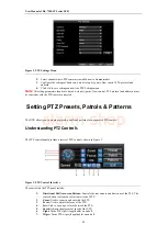
Page 90: ...camera Call Preset Call a PTZ preset Call Patrol Call a PTZ sequence Call Pattern Call a PTZ pattern Preset Settings Enter PTZ preset configuration menu Patrol Settings Enter PTZ sequence configuration menu Pattern Settings Enter PTZ pattern configuration menu PTZ Menu Enter PTZ control menu PTZ Settings Enter PTZ settings menu Configuring PTZ Settings Settings for a PTZ camera must be configured ...

Page 91: ...DVR allows you to program presets patrols and patterns for a connected PTZ camera Understanding PTZ Controls The PTZ control panel provides a series of PTZ controls shown in Figure 3 Figure 3 PTZ Control Interface The controls on the PTZ panel include 1 Directional Pad Auto scan Buttons Controls the movements and directions of the PTZ The center button is also used to start auto scan of PTZ 2 Zoom...

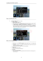
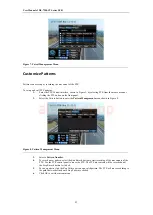
Page 92: ...t location Clear Preset Select a Preset number and click the Clear button to delete the preset You may also select the Clear All button to delete all presets Call Preset Select a Preset and click the Call button Figure 4 Preset Management Menu Note Only valid presets can be called and deleted Customizing Patrols Patrols can be programmed to move the PTZ to different key points and make it stay the...

Page 93: ... time span to stay at the corresponding key point The Speed defines the rate at which the PTZ will move to the current preset Figure 6 Patrol Configuration Menu 4 Click OK to return to Patrol Management menu and repeat steps 2 3 to configure other key points 5 After all key points have been configured click the defined key point No and then click Add button to complete the settings 6 Click OK butt...

Page 94: ...button to enter the Pattern Management menu shown in Figure 8 Figure 8 Pattern Management Menu 3 Select a Pattern Number 4 To record a new pattern select the Run Record button to start recording of the movements of the PTZ Use the PTZ control panel to move the PTZ The PTZ movements will be recorded until the Stop Record button is clicked 5 To run a pattern click the Run Pattern button on a valid p...

Page 95: ...User Manual of DS 7200 ST Series DVR 94 C H A P T E R 1 0 Camera Management alarm shop ...

Page 96: ...No and click the Set button 3 Configure desired OSD settings as shown in Figure1 Figure 1 OSD Settings Menu 4 Click the Set button to edit the OSD display position including the camera name position and the date time display position Video Input Output Mode Settings To configure the video output mode settings 1 Click Menu Settings General to enter the General Settings menu 2 Click the More Setting...

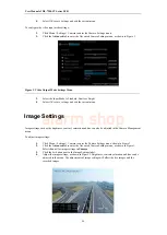
Page 97: ... Image Settings Image settings such as the brightness contrast saturation and hue can also be adjusted in the Camera Management menu To adjust image settings 1 Click Menu Settings Camera to enter the Camera Settings menu shown in Figure 3 2 Click the Advanced tab to enter the Advanced Camera Settings menu as shown in Figure1 Select channel for image settings in Camera 3 Click the Set button next t...

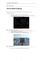
Page 98: ... menu 2 Click the Advanced tab to enter the Advanced Camera Settings menu as shown in Figure 4 Select channel for privacy mask settings in Camera Figure 4 Advanced Camera Settings Menu 3 Check the Mask checkbox to enable feature 4 Click the Area Settings button to enter Area Settings menu 5 Set mask area as shown in Figure 5 Up to 4 areas can be configured Figure 5 Setting Mask Area 6 Select Exit ...

Page 99: ...User Manual of DS 7200 ST Series DVR 98 C H A P T E R 1 1 HDD Management alarm shop ...

Page 100: ...HDD to be initialized 3 Click the Init button 4 Select OK button to start initialization After the HDD has been initialized the status of the HDD will change from Abnormal to Normal Setting HDD Groups Your DVR can separate multiple HDDs into groups Videos from specified channels can be set to be recorded onto a particular HDD group To set a HDD group 1 Click Menu HDD to enter the HDD Management me...

Page 101: ...e set to read only or read write R W Setting HDD to Read Only A HDD can be set to read only to avoid important recorded files from being overwritten when the HDD becomes full To set a HDD to read only 1 Click Menu HDD to enter the HDD Management menu 2 Select HDD to be protected 3 Select the Property button to enter the Property Settings menu as shown in Figure 3 Figure 3 HDD Property Settings Men...

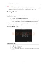
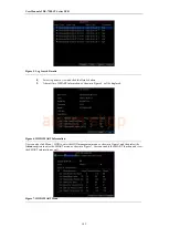
Page 102: ...D is in working order If it is listed as Abnormal and has already been initialized the HDD needs to be replaced If the HDD is Uninitialized you will need to initialize it before it can be use in your DVR Please refer to Initializing HDDs for further instructions You may also view the SMART information of installed HDD SMART abbreviation for Self Monitoring Analysis and Reporting Technology is a mo...

Page 103: ...nformation as shown in Figure 6 will be displayed Figure 6 HDD SMART Information User can also click Menu HDD to enter the HDD management menu as shown in Figure1 and then select the Advance option to enter the SMART menu as shown in Figure 7 User can enable the SMART function and view the SMART information as well Figure 7 HDD SMART Menu alarm shop ...

Page 104: ...xception to enter Exception menu shown in Figure 8 Figure 8 Exception Menu 2 Select HDD Error under Exception Type 3 Select trigger action Trigger actions are further explained in Understanding Exception Trigger Options Note The Trigger Alarm Output option is invalid for DS 7200HVI ST SE DS 7200HFI ST SE DS 7200HVI ST SN and DS 7200HFI ST SN models as they provide no alarm in out alarm shop ...

Page 105: ...User Manual of DS 7200 ST Series DVR 104 C H A P T E R 1 2 DVR Management alarm shop ...

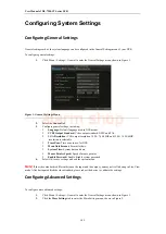
Page 106: ...024 768 60HZ and 1280 1024 60HZ resolution is selectable Time Zone Time zone to use for DVR Menu Date Format Format for date System Time System time and date Mouse Pointer Speed Speed of mouse pointer Enable Password Enable disable system password 4 Select OK to save settings and exit the current menu Note If the video standard is different between the input and the output you may notice flickerin...

Page 107: ...utput Mode Select the menu output mode to Auto VGA HDMI or CVBS When the Auto is selected the system will automatically detect whether the VGA HDMI or CVBS interface is connected Note DS 7208HFI ST and DS 7216HFI ST can be customized with optional HDMI output interface Output Mode Set the video output mode to Standard or Brilliant according to different environmental conditions 4 Select OK to save...

Page 108: ...a serial device directly to the DVR The serial device will be controlled remotely by the PC through the network and the protocol of the serial device Managing User Accounts By default settings your DVR is configured with the user name of admin and the password of 12345 The Administrator has the authority to add delete or configure the user parameters Adding a New User To add a new user 1 Click Men...

Page 109: ...rmission button to enter the Permission Settings menu shown in Figure 6 Figure 6 Permission Settings Menu 7 Configure permission for local settings under Local Permission tab The local settings include Local Log Search Search and view logs of DVR Local Configuration Configure and restore parameters to factory defaults Introduce settings to or export settings from DVR Local Advanced Operation HDD m...

Page 110: ...Figure 8 The channel settings include Figure 8 Camera Permission Settings Menu Remote Live View Select and view live video over the network Local Manual Record Locally start and stop manual recording on any of the channels Remote Record Starting Remotely start and stop manual recording on any of the channels Local Playback Locally play recorded files that are on the DVR Remote Playback Remotely pl...

Page 111: ...rmissions settings are defined in the Adding a New User section described above 6 Click the OK button to save and exit the menu Importing Exporting Configuration Configuration information from your DVR can be exported to a USB device and imported into another DVR This will allow you to efficiently setup the same configuration on numerous DVRs To import or export DVR configuration 1 Click Menu Main...

Page 112: ... DST Settings Menu 3 Check the checkbox before the Enable DST item 4 Set the start tine and end time of DST period The end time must be later than the start time When the DST period ends the system will reverts to the standard local time 5 Set the DST bias to 30 minutes 60 minutes 90 minutes or 120 minutes 6 Click the OK button to save and exit menu Updating System Firmware The firmware on your DV...

Page 113: ...he PC and copy the firmware into the root directory of TFTP 2 Enter the Firmware Update menu by clicking Menu Maintenance Upgrade 3 Select the FTP tab shown in Figure 13 Figure 13 FTP Firmware Update 4 Input the FTP server address 5 Select Upgrade to begin update process 6 After the system firmware has been update reboot the DVR Note If the DVR fails to update please contact your system supplier f...

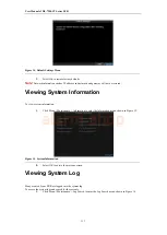
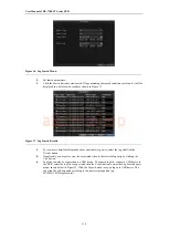
Page 114: ...Information To view system information 1 Click Menu Maintenance Information to enter the Information menu shown in Figure 15 Figure 15 System Information 2 Select OK to exit to the previous screen Viewing System Log Many events of your DVR are logged into the system log To access the system logs and search for these events 1 Click Menu Maintenance Log Search to enter the Log Search menu shown in F...

Page 115: ...try select the log and click the Details button 5 If applicable you may also view the associated video to the selected log entry by clicking the Play button 6 Log files can also be exported onto a USB device To export a log file connect a USB device to the DVR select the log file to export and click the Export button to enter the Log Search Export menu shown below in Figure 17 Click the Export but...

Page 116: ...User Manual of DS 7200 ST Series DVR 115 Figure 18 Log Search Export Menu 7 Click Cancel to exit the current menu alarm shop ...

Page 117: ...User Manual of DS 7200 ST Series DVR 116 C H A P T E R 1 3 Appendix alarm shop ...

Page 118: ...or a networked device such as a router or computer system using the Internet Protocol Suite to notify a domain name server to change in real time ad hoc the active DNS configuration of its configured hostnames addresses or other information stored in DNS Hybrid DVR A hybrid DVR is a combination of a DVR and NVR NTP Acronym for Network Time Protocol A protocol designed to synchronize the clocks of ...

Page 119: ...are no fluorescent lamps in use Why does the PTZ seem unresponsive If the PTZ seem unresponsive please check 1 Check that the RS 485 cable is properly connected 2 Check that the dome decoder type is correct 3 Check that the dome decoder speed configuration is correct 4 Check that the dome decoder address bit configuration is correct 5 Check to make sure that the main board RS 485 interface is not ...

Reviews: