background image

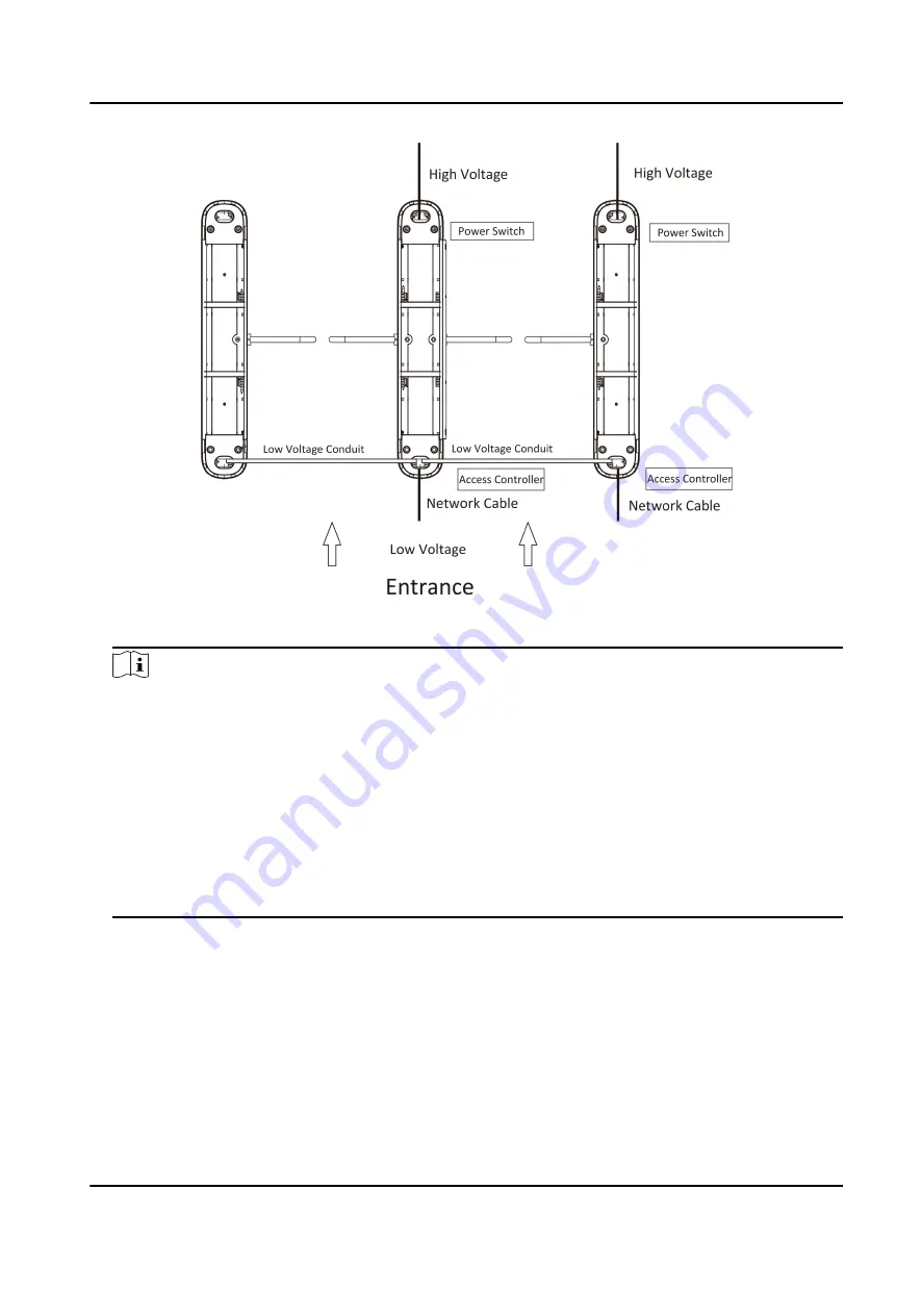
Figure 2-2 System Wiring Diagram (General Wiring)

Note

• The supplied interconnecting cable length is 3.75 m. If you need a longer one, you can buy a

new accessory.

• The suggested inner diameter of the low voltage conduit is larger than 30 mm.

• If you want to bury both of the AC power cord and the low voltage cable at the entrance, the

two cables should be in separated conduits to avoid interference.

• If more peripherals are required to connect, you should increase the conduit diameter or

bury another conduit for the external cables.

• The external AC power cord should be double-insulated.

• The network cable must be CAT5e or the network cable has better performance. And the

suggested network cable length should be less than 100 m.

DS-K3B411X Series Swing Barrier Quick Start Guide

4

Summary of Contents for DS-K3B411X Series

Page 1: ...DS K3B411X Series Swing Barrier Quick Start Guide ...

Page 2: ... HIKVISION BE LIABLE TO YOU FOR ANY SPECIAL CONSEQUENTIAL INCIDENTAL OR INDIRECT DAMAGES INCLUDING AMONG OTHERS DAMAGES FOR LOSS OF BUSINESS PROFITS BUSINESS INTERRUPTION OR LOSS OF DATA CORRUPTION OF SYSTEMS OR LOSS OF DOCUMENTATION WHETHER BASED ON BREACH OF CONTRACT TORT INCLUDING NEGLIGENCE PRODUCT LIABILITY OR OTHERWISE IN CONNECTION WITH THE USE OF THE PRODUCT EVEN IF HIKVISION HAS BEEN ADVI...

Page 3: ...evice with facial recognition features biometrics data is stored in your device with encryption method for fingerprint device only fingerprint template will be saved which is impossible to reconstruct a fingerprint image As data controller you are advised to collect store process and transfer data in accordance with the applicable data protection laws and regulations including without limitation c...

Page 4: ...ul interference to radio or television reception which can be determined by turning the equipment off and on the user is encouraged to try to correct the interference by one or more of the following measures Reorient or relocate the receiving antenna Increase the separation between the equipment and receiver Connect the equipment into an outlet on a circuit different from that to which the receive...

Page 5: ...ethis info 2006 66 EC battery directive This product contains a battery that cannot be disposed of as unsorted municipal waste in the European Union See the product documentation for specific battery information The battery is marked with this symbol which may include lettering to indicate cadmium Cd lead Pb or mercury Hg For proper recycling return the battery to your supplier or to a designated ...

Page 6: ...wer source during servicing Keep body parts away from motors Disconnect the power source during servicing To prevent possible hearing damage do not listen at high volume levels for long periods All the electronic operation should be strictly compliance with the electrical safety regulations fire prevention regulations and other related regulations in your local region Do not connect several device...

Page 7: ...combustible surface only Install the equipment according to the instructions in this manual To prevent injury this equipment must be securely attached to the floor wall in accordance with the installation instructions Stainless steel may be corroded in some circumstances You need to clean and care the device by using the stainless steel cleaner It is suggested to clean the device every month Do no...

Page 8: ...structions provided by the battery manufacturer Biometric recognition products are not 100 applicable to anti spoofing environments If you require a higher security level use multiple authentication modes Do not stay in the lane when the device is rebooting RISK OF EXPLOSION IF BATTERY IS REPLACED BY AN INCORRECT TYPE DISPOSE OF USED BATTERIES ACCORDING TO THE INSTRUCTIONS SUITABLE FOR MOUNTING ON...

Page 9: ...Pedestal DS K3B411X R Right Pedestal DS K3B411X LS Left Pedestal No Barrier DS K3B411X MS Middle Pedestal Single Barrier Scan the QR code to get User Manual of Swing Barrier Note that mobile data charges may apply if Wi Fi is unavailable Figure 1 1 QR Code DS K3B411X Series Swing Barrier Quick Start Guide viii ...

Page 10: ...re Network Switch Optional 18 4 5 Terminal Description 20 4 5 1 Main Control Board Terminal Description 20 4 5 2 Sub Control Board Terminal Description 21 4 5 3 BUS Terminal Description 21 4 5 4 Access Control Board Terminal Description 23 4 5 5 Access Control Board Serial Port ID Description 28 4 5 6 RS 485 Wiring 33 4 5 7 RS 232 Wiring 34 4 5 8 Barrier Control Wiring 34 4 5 9 Alarm Output Wiring...

Page 11: ...on 42 6 1 Activate via SADP 42 6 2 Activate Device via Client Software 43 Appendix A DIP Switch Description 45 Appendix B Event and Alarm Type 46 Appendix C Table of Audio Index Related Content 47 Appendix D Error Code Description 48 Appendix E Communication Matrix and Device Command 50 DS K3B411X Series Swing Barrier Quick Start Guide x ...

Page 12: ...aining open closed mode selectable Bidirectional Entering Exiting lane The barrier opening and closing speed can be configured according to the visitor flow The barrier will be locked or stop working when people are nipped Anti forced accessing The barrier will be locked automatically without open barrier signal It can bear the force of up to 50 N m Self detection Self diagnostics and automatic al...

Page 13: ...on settings System will cancel the passing permission if a person does not pass through the lane within the valid passing duration Opens Closes barrier according to the schedule template Up to 60 000 cards can be added Up to 180 000 card swiping records can be saved DS K3B411X Series Swing Barrier Quick Start Guide 2 ...

Page 14: ...he other pedestals Note The distance between the nearest two line is L 200 mm L represents the lane width 3 Slot on the installation surface and dig installation holes according to the hole position diagram Figure 2 1 Hole Position Diagram 4 Bury cables Each lane buries 1 network cable and 1 high voltage cable For details see the system wiring diagram below DS K3B411X Series Swing Barrier Quick St...

Page 15: ...the low voltage cable at the entrance the two cables should be in separated conduits to avoid interference If more peripherals are required to connect you should increase the conduit diameter or bury another conduit for the external cables The external AC power cord should be double insulated The network cable must be CAT5e or the network cable has better performance And the suggested network cabl...

Page 16: ... cable by yourself If you want to bury both of the AC power cord and the low voltage cable at the entrance the two cables should be in separated conduits to avoid interference If more peripherals are required to connect you should increase the conduit diameter or bury another conduit for the external cables The external AC power cord should be double insulated The network cable must be CAT5e or th...

Page 17: ... clear the installation base Steps Note The device should be installed on the concrete surface or other non flammable surfaces In order to prevent stainless steel from rusting due to dirt during the construction process it is recommended to tear off the protective film after the device is installed There may be residual glue at the film cutting position and it is recommended to wipe the film with ...

Page 18: ... than 20 mm or the surface may be scratched Figure 3 2 Installation Distance Without Face Recognition Terminal Face recognition terminal installed If the installation area is too close to the wall make sure the distance between the pedestal and the wall should be more than 20 mm or the surface may be scratched DS K3B411X Series Swing Barrier Quick Start Guide 7 ...

Page 19: ...Figure 3 3 Installation Distance With Face Recognition Terminal The dimension is as follows DS K3B411X Series Swing Barrier Quick Start Guide 8 ...

Page 20: ...the turnstile to avoid water from entering 4 According to the entrance and exit marks on the pedestals move the pedestals to the corresponded positions Note Make sure the installation holes on the pedestals and the base are aligned with each other 5 Secure the pedestals with expansion bolts Note Do not immerse the pedestal in the water In special circumstances the immersed height should be no more...

Page 21: ...Figure 3 6 Installation Footprint DS K3B411X Series Swing Barrier Quick Start Guide 10 ...

Page 22: ...the electric supply is between 85 VAC and 264 VAC 50 to 60 Hz The picture displayed below describes each component s position on the turnstile Note The diagram is for reference only Figure 4 1 Components Diagram 1 Note The reinstalled supercapacitor needs to be powered on for at least 3 minutes before it can work normally The picture displayed below describes the IR adapter and the IR sending rece...

Page 23: ...R boards on the right side of the middle pedestal are the IR sending boards Warning tags can be viewed on the side panel of each pedestal Safety Instructions can be viewed on the middle panel inside the pedestal 4 2 Wiring Electric Supply Wire electric supply with the switch in the pedestal Terminal L and terminal N are on the switch while terminal PE should connect to a ground wire yellow and gre...

Page 24: ...be wired reversely Do not wire the input and output terminal reversely To avoid people injury and device damage when testing the ground resistance of the equipotential points should not be larger than 2 Ω 4 3 Wire Interconnecting Cable You should use interconnecting cables to connect the main lane board and the sub lane board for components communication The picture displayed below describes the c...

Page 25: ...uctions below to connect the interconnecting cable Figure 4 4 Connect Interconnecting Cable 4 3 1 Pull Interconnecting Cable Steps 1 Use the key to unlock the upper lock of the pedestals and remove the top cover DS K3B411X Series Swing Barrier Quick Start Guide 14 ...

Page 26: ...Figure 4 5 Dissemble Top Cover 2 Dissemble the card presenting board DS K3B411X Series Swing Barrier Quick Start Guide 15 ...

Page 27: ...Figure 4 6 Dissemble Card Presenting Board 3 Dissemble the card reader module DS K3B411X Series Swing Barrier Quick Start Guide 16 ...

Page 28: ...he interconnecting cable out from the bottom up with pull out tool and other wiring operations can be performed Note Interconnecting cable includes a network cable and a power supply cable of 24 V DS K3B411X Series Swing Barrier Quick Start Guide 17 ...

Page 29: ...out Interconnecting Cable 4 4 Wire Network Switch Optional Connect the network cable and the network switch Steps 1 Use the key to open the top cover of the pedestal DS K3B411X Series Swing Barrier Quick Start Guide 18 ...

Page 30: ...Figure 4 9 Open Top Cover 2 Attach the network switch to the position shown in the figure with adhesive DS K3B411X Series Swing Barrier Quick Start Guide 19 ...

Page 31: ... lane controller and sub lane controller which controls the IR beams motor and other components work 4 5 1 Main Control Board Terminal Description The main lane control board contains power input BUS interface interconnecting interface supercapacitor interface IR interface barrier position control board interface and motor drive interface The picture displayed below is the main control board diagr...

Page 32: ...tor drive interface The picture displayed below is the sub control board diagram Figure 4 12 Sub Control Board Terminal 4 5 3 BUS Terminal Description You can connect the lane controller light board fan TAMPER lane control board card reader face recognition terminal QR code scanner etc via the BUS terminal Note Part of the wiring has been completed at the factory please connect according to actual...

Page 33: ...ck GND grounding Table 4 2 BUS Terminal in Sub Lane Controller Left Pedestal Terminal Name Description Lane Controller Light Board 1 Connects lane controller light board 1 Lane Controller Light Board 2 Connects lane controller light board 2 Fan 1 Connects fan 1 Fan 2 Connects fan 2 TAMPER Connects TAMPER Lane Controller Board Connect main lane controller board Port 5 Note External card reader is r...

Page 34: ...access Red 12 V connects 12 VDC power supply terminal Yellow 485E 232E card reader RS 485E RS 232E access terminal Blue 485E 232E card reader RS 485E RS 232E access terminal Black GND grounding Port 6 Note External face recognition terminal is recommended to access Red 12 V connects 12 VDC power supply terminal Yellow 485F 232F card reader RS 485F RS 232F access terminal Blue 485F 232F card reader...

Page 35: ... Grounding RS 485 Interface RS 485 C Connect to Card Reader RS485 RS 485 card reader ID factory DIP is 1 and 3 1 represents the passage entrance and 3 represents the passage exit UART 1 in the main control board corresponds to the entrance card reader and UART 5 in the main RS 485 C Connect to Card Reader RS485 GND Grounding DS K3B411X Series Swing Barrier Quick Start Guide 24 ...

Page 36: ...one with the DIP 4 and the other with the DIP 3 The card reader 3 and the card receiver are used together the ordinary user swipes the card on the card reader 4 and the guest user swipes the card on the card reader 3 This is the RS 485 interface which cannot be switched by dialing Power Output 2 5 V 5 VDC Power Output G Grounding DS K3B411X Series Swing Barrier Quick Start Guide 25 ...

Page 37: ...l QR code scanner you need to connect it through the RS 232 interface here After the cable is connected to the RS 232 interface it passes through the embedded pipe and connects with the QR code on the left RS 232 G Connect to RS 232G RS 232 G Connect to Card Reader RS 232G G Grounding RS 232 H Connect to RS 232H RS 232 H Connect to Card Reader RS 232H Power Input 24 V 24 VDC Power Input GND Ground...

Page 38: ...t etc G Grounding C2 Event Alarm Input 2 Exit Button B2 Door 2 Signal Input G Grounding B1 Door 1 Signal Input Door Lock Relay D1 Door 1 Relay Output Dry Contact If necessary the door lock relay can be used to control the third party barrier switch D1 controls the door opening for ordinary entrance and D2 controls the door opening for ordinary exit D1 D2 Door 2 Relay Output Dry Contact If necessar...

Page 39: ...e input G Grounding Note You can swtich between RS 485 and RS 232 via the DIP switch on the access control board For details about DIP switch and swiching method see Access Control Board Serial Port ID Description For details about DIP switch operation see DIP Switch Description 4 5 5 Access Control Board Serial Port ID Description You can set the device mode switch the communication mode of the c...

Page 40: ... device mode DIP 2 to 5 can set the RS 485 RS 232 interface and DIP B can also be used to initialize the device The UART corresponding to the DIP Switch is shown in the figure below Figure 4 15 UART No Description DS K3B411X Series Swing Barrier Quick Start Guide 29 ...

Page 41: ... Test Mode 3 Memory Mode Enable Memory Mode Disable Memory Mode 4 Keyfob Paring Mode Enable Keyfob Paring Mode Disable Keyfob Paring Mode 5 to 8 Passing Mode Controlled Bi direction Controlled Entrance and Prohibit Exit Controlled Entrance and Free Exit Free Bi direction Free Entrance and Controlled Exit DS K3B411X Series Swing Barrier Quick Start Guide 30 ...

Page 42: ... 6 ON UART 5 is RS 485E Interface 7 Reserved 8 Default is OFF You can dial to ON for initial operation DIP C 1 to 3 UART 6 ON UART 6 is RS 232F Interface 4 to 6 ON UART 6 is RS 485F Interface 7 Reserved 8 Reserved DIP D 1 to 3 UART 1 ON UART 1 is RS 232A Interface 4 to 6 ON UART 1 is RS 485A Interface 7 Reserved 8 Reserved DIP E 1 to 3 UART 3 ON UART 3 is RS 232C Interface DS K3B411X Series Swing ...

Page 43: ...3 4 to 6 7 and 8 of DIP B DIP C DIP D and DIP E cannot be turned ON at the same time The reserved UART terminal positions in the turnstile and their corresponded UART No are as follows Note The diagram is for reference only Figure 4 16 Interface and Corresponded UART No DS K3B411X Series Swing Barrier Quick Start Guide 32 ...

Page 44: ...R code scanner card reader card recycler text screen and face recognition terminal Take the wiring of RS 485 card reader as an example For details about text screen see Configuring Screen Parameters in User Manual of iVMS 4200 AC Client Software DS K3B411X Series Swing Barrier Quick Start Guide 33 ...

Page 45: ...oftware Take the wiring of text screen as an example 4 5 8 Barrier Control Wiring By default the barrier has connected with the access control board The lane control board can control the barrier status If possible the device can connect with a third party lane control board to control the third party barriers Interface D1 controls barrier opening for entrance while interface D2 controls barrier o...

Page 46: ...Note Use the jumper cap to switch the relay status For details see Barrier Control Relay Output Mode Entering Wiring Exiting Wiring DS K3B411X Series Swing Barrier Quick Start Guide 35 ...

Page 47: ...4 5 9 Alarm Output Wiring Note For details about changing the relay output status via the jumper cap see Alarm Relay Output Mode NO NC DS K3B411X Series Swing Barrier Quick Start Guide 36 ...

Page 48: ...exit prohibited bi direction prohibited entrance and free exit Memory Mode By default the memory mode is enabled When multiple cards are presented and authenticated it allows multiple persons passing through the lane When it counts the passing people number is equal to the card presented times or no person passing through the lane after the last person passing the barriers will be closed Note You ...

Page 49: ...he access control board to the ON side Figure 5 1 Initialization Jumper Cap 2 Disconnect the power and reboot the device The device buzzer buzzes a long beep 3 When the beep stopped set the No 8 switch to the OFF side and reboot the turnstile to take effect 4 Disconnect the power and power on the device again Caution The initialization of the device will restore all the parameters to the default s...

Page 50: ...ol relay on the access control board is as below Figure 5 2 Jumper Cap Location Barrier Control Relay Output Mode The jumper cap position of barrier opening NO is as below Figure 5 3 Barrier Opening NO The jumper cap position of barrier closing NC is as below DS K3B411X Series Swing Barrier Quick Start Guide 39 ...

Page 51: ...tput Mode NO NC The jumper cap of the alarm relay on the access control board is as below Figure 5 5 Jumper Cap Location Alarm Relay Output Mode The jumper cap position of alarm opening NO is as below Figure 5 6 Alarm Opening NO DS K3B411X Series Swing Barrier Quick Start Guide 40 ...

Page 52: ...The jumper cap position of alarm closing NC is as below Figure 5 7 Alarm Closing NC Note The default status is NO DS K3B411X Series Swing Barrier Quick Start Guide 41 ...

Page 53: ...e within the same subnet The following steps show how to activate a device and modify its IP address For batch activation and IP addresses modification refer to User Manual of SADP for details Steps 1 Run the SADP software and search the online devices 2 Find and select your device in online device list 3 Input new password admin password and confirm the password Caution STRONG PASSWORD RECOMMENDE...

Page 54: ...erly Steps Note This function should be supported by the device 1 Enter the Device Management page 2 Click on the right of Device Management and select Device 3 Click Online Device to show the online device area The searched online devices are displayed in the list 4 Check the device status shown on Security Level column and select an inactive device 5 Click Activate to open the Activation dialog ...

Page 55: ...recommend you change your password regularly especially in the high security system changing the password monthly or weekly can better protect your product Proper configuration of all passwords and other security settings is the responsibility of the installer and or end user 7 Click OK to activate the device DS K3B411X Series Swing Barrier Quick Start Guide 44 ...

Page 56: ... right side is from the low bit to the high bit When the switch is towards ON it means the switch is enabled otherwise the switch is off If you set the DIP switch like the figure displayed below its binary value is 00001100 and its decimal value is 12 DS K3B411X Series Swing Barrier Quick Start Guide 45 ...

Page 57: ...se Passing Visual and Audible Force Accessing None Climb over Barrier Visual and Audible Overstay Visual and Audible Passing Timeout None Intrusion Visual and Audible Free Passing Authentication Failed Visual Barrier Obstructed None DS K3B411X Series Swing Barrier Quick Start Guide 46 ...

Page 58: ...t 3 Card No and fingerprint mismatch 4 Climbing over the barrier 5 Reverse passing 6 Passing timeout 7 Intrusion 8 Force accessing 9 Tailgating 10 No permissions 11 Authentication time out 12 Authentication failed 13 Expired card 14 Stay out of time DS K3B411X Series Swing Barrier Quick Start Guide 47 ...

Page 59: ...r IR Board Triggered 05 Upper IR Board 10 Offline 34 The Sixth IR Beam on Upper IR Board Triggered 06 Upper IR Board 11 Offline 35 The Seventh IR Beam on Upper IR Board Triggered 07 Upper IR Board 12 Offline 36 The Eighth IR Beam on Upper IR Board Triggered 08 Lower IR Board 1 Offline 37 The Ninth IR Beam on Upper IR Board Triggered 09 Lower IR Board 2 Offline 38 The Tenth IR Beam on Upper IR Boar...

Page 60: ...8 The Eighth IR Beam on Lower IR Board Triggered 20 Light Board Offline Entrance 49 The Ninth IR Beam on Lower IR Board Triggered 21 Light Board Offline Exit 50 The Tenth IR Beam on Lower IR Board Triggered 22 IR Adapter Offline Up 51 The Eleventh IR Beam on Lower IR Board Triggered 23 IR Adapter Offline Low 52 The Twelfth IR Beam on Lower IR Board Triggered 24 CAN Bus Exception 53 Upper IR Board ...

Page 61: ...Hikvision access control and video intercom devices Figure E 1 QR Code of Communication Matrix Device Command Scan the following QR code to get the device common serial port commands Note that the command list contains all commonly used serial ports commands for all Hikvision access control and video intercom devices Figure E 2 Device Command DS K3B411X Series Swing Barrier Quick Start Guide 50 ...

Page 62: ...UD21908B ...

Reviews: