


Chapter 2 System Wiring
The preparation before installation and wiring.
Steps
1. Draw a central line on the installation surface of the left or right pedestal.
2. Draw other parallel lines for installing the other pedestals.
Note
The distance between the nearest two line is L+100 mm. L represents the lane width.
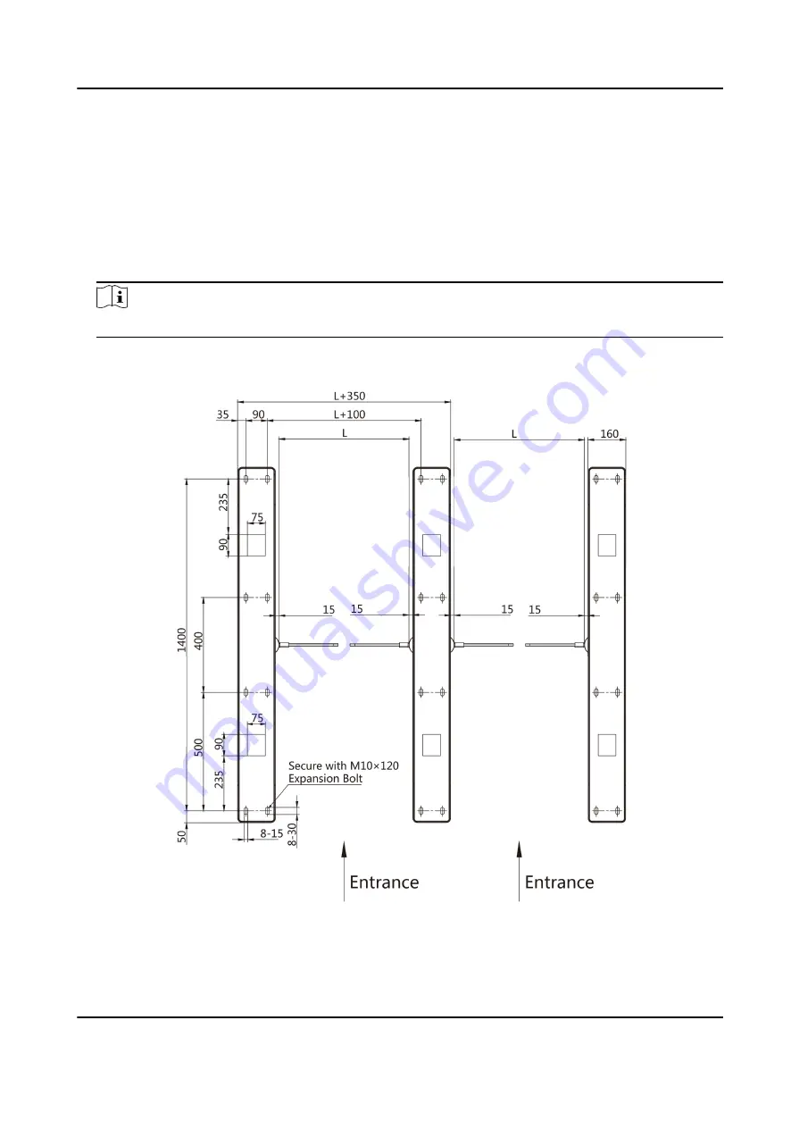
3. Slotting on the installation surface and dig installation holes according to the hole position
diagram.
Figure 2-1 Hole Position Diagram
DS-K3B801SX Series Swing Barrier Quick Start Guide
3
Summary of Contents for DS-K3B801SX Series
Page 1: ...DS K3B801SX Series Swing Barrier Quick Start Guide ...
Page 34: ...Figure 4 13 Remove Top Cover DS K3B801SX Series Swing Barrier Quick Start Guide 23 ...
Page 49: ...DS K3B801SX Series Swing Barrier Quick Start Guide 38 ...
Page 51: ...Entering Wiring Exiting Wiring DS K3B801SX Series Swing Barrier Quick Start Guide 40 ...
Page 58: ...Alarm Relay Output Mode NC DS K3B801SX Series Swing Barrier Quick Start Guide 47 ...
Page 72: ...UD22971B ...


