• For any requirements, the door lock can control the door barrier status of the third party. D1
controls the barrier opening for entrance, while D2 controls the door opening for exit. For
details, see Barrier Control Relay Output Mode .
• C3 and C4 in the event input can also be people counting interface. C3 controls people counting
for entrance, while C4 controls people counting for exit. When the access control board detects
signals in C3 and C4, the people number will be accumulated. For detailed information about
people counting and people number, see Configuring People Counting Parameters in User
Manual of iVMS-4200 AC Client Software.
• For detailed information about the DIP switch, see DIP Switch .
4.5.4 Access Control Board Serial Port ID Description
You can use the jumper cap on the access control board to switch the interface communication
mode. For details about switching between RS-232 and RS-485 communication type, see Switching
RS-485/RS-232 Mode.
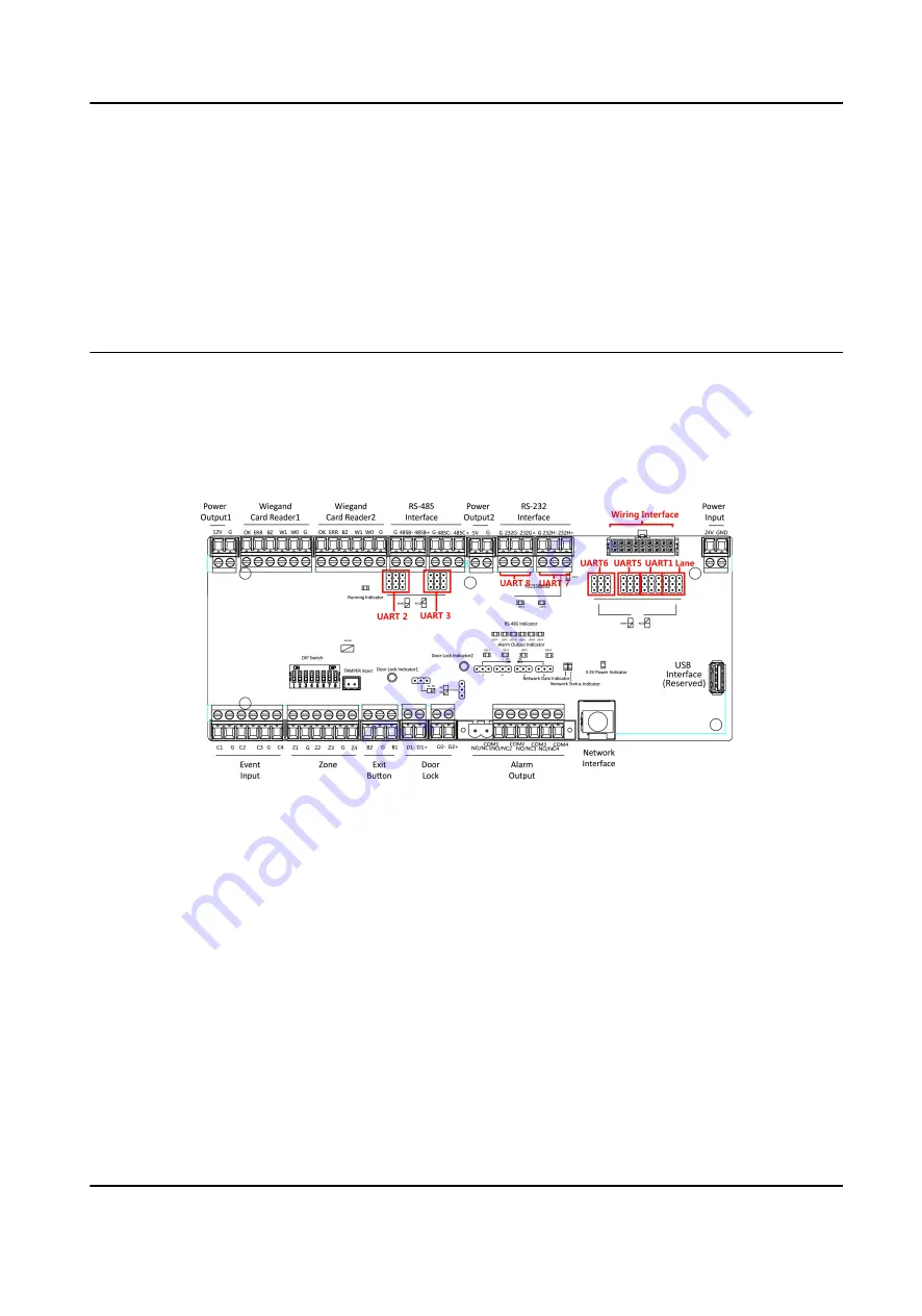
Figure 4-9 Access Control Board
According to the picture above, the RS-485 serial port corresponds to UART2 and UART3. RS-232
serial port is corresponded to UART7 and UART8. Wiring Interface is corresponded to UART1,
UART4, UART6, UART6, and Lane.
The access control board descriptions are as follows:
UART2/UART3 Jumper Cap
Reserved serial port. Use the jumper cap to switch the serial port communication mode. You
can switch between the RS-485 communication mode and the RS-232 communication mode. By
default, it is in RS-485 communication mode.
UART6 Jumper Cap
Use the jumper cap to switch the serial port communication mode with the sub lane controller.
You can switch between the RS-232 communication mode and the RS-485 communication
mode. By default, it is in RS-232 communication mode.
DS-K3Y501SX Series Flap Barrier Quick Start Guide
17

