background image

6.6.5 Change Person to Other Organization

You can move the person to another organization if needed.
Steps
1. 
Select the person in the list and click Change Organization.
2. Select the organization to move the person to.
3. Click OK to save the settings.

6.6.6 Add Person in Batch

Enter a short description of your task here (optional).

Before You Start

Enter the prerequisites here (optional).

Enter the context of your task here (optional).
Steps
1. 
Enter your first step here.

Enter the result of your step here (optional).

Example

Enter an example that illustrates the current task (optional).

What to do next

Enter the tasks the user should do after finishing this task (optional).

6.6.7 Issue Card in Batch

You can issue multiple cards for the person with no card issued in batch.
Steps
1. 
Click Batch Issue Cards to enter the dialog page. All the added person with no

card issued will display in the Person(s) with No Card Issued list.

Video Intercom Face Recognition Door Station User Manual

44

Summary of Contents for DS-KD9613-E6

Page 1: ...Video Intercom Face Recognition Door Station User Manual...

Page 2: ...jurisdictions Other trademarks and logos mentioned are the properties of their respective owners Disclaimer TO THE MAXIMUM EXTENT PERMITTED BY APPLICABLE LAW THIS MANUAL AND THE PRODUCT DESCRIBED WITH...

Page 3: ...ESTRUCTION THE DEVELOPMENT OR PRODUCTION OF CHEMICAL OR BIOLOGICAL WEAPONS ANY ACTIVITIES IN THE CONTEXT RELATED TO ANY NUCLEAR EXPLOSIVE OR UNSAFE NUCLEAR FUEL CYCLE OR IN SUPPORT OF HUMAN RIGHTS ABU...

Page 4: ...will or could result in death or serious injury Caution Indicates a potentially hazardous situation which if not avoided could result in equipment damage data loss performance degradation or unexpecte...

Page 5: ...ter Never attempt to disassemble the device yourself We shall not assume any responsibility for problems caused by unauthorized repair or maintenance Caution Do not drop the device or subject it to ph...

Page 6: ...in hazard of explosion Replace with the same or equivalent type only Dispose of used batteries according to the instructions provided by the battery manufacturer Improper replacement of the battery wi...

Page 7: ...io or television reception which can be determined by turning the equipment off and on the user is encouraged to try to correct the interference by one or more of the following measures Reorient or re...

Page 8: ...ion points For more information see www recyclethis info 2006 66 EC battery directive This product contains a battery that cannot be disposed of as unsorted municipal waste in the European Union See t...

Page 9: ...t isotropically radiated power e i r p is not more than that necessary for successful communication Conform ment la r glementation d Industrie Canada le pr sent metteur radio peut fonctionner avec une...

Page 10: ...Output Wiring 9 3 Installation 10 3 1 Junction Box Sales Seperately 10 3 2 Wall Mounting with Junction Box 11 4 Activation 12 4 1 Activate Device Locally 12 4 2 Activate Device via Client Software 13...

Page 11: ...ace 20 6 Configuration via Client Software 22 6 1 Edit Network Parameters 22 6 2 Add Device 22 6 2 1 Add Online Device 22 6 2 2 Add Device by IP Address 23 6 2 3 Add Device by IP Segment 23 6 3 Remote...

Page 12: ...mation from Device 43 6 6 5 Change Person to Other Organization 44 6 6 6 Add Person in Batch 44 6 6 7 Issue Card in Batch 44 6 6 8 Permission Settings 46 6 7 Video Intercom Settings 47 6 7 1 Receive C...

Page 13: ...model Refers to actual device With Fingerprint Module Figure 1 1 Front and Side Panel Table 1 1 Appearance and Description No Description 1 Light 2 Camera 3 Microphone 4 Screen 5 Fingerprint Reconitio...

Page 14: ...Module Figure 1 2 Front and Side Panel Table 1 2 Appearance and Description No Description 1 Light 2 Camera 3 Microphone 4 Screen 5 Card Reader Area 6 TAMPER Video Intercom Face Recognition Door Stati...

Page 15: ...cription of Terminal and Interface Name Interface Description Power Input DC 12 V 12 VDC Power Input ALARM OUT AO1 Alarm Relay Output 1 AO1 AO2 Alarm Relay Output 2 AO2 ALARM IN AI1 Alarm Input 1 AI2...

Page 16: ...rd Reader Buzzer Output W0 Data Input Interface Wiegand Card Reader Data0 W1 Data Input Interface Wiegand Card Reader Data1 GND Grounding 12V Power Supply Output GND Grounding DOOR NO1 Door Lock Relay...

Page 17: ...rminal NC1 COM1 is set as default for accessing electric strike Terminal NO1 COM1 is set as default for accessing magnetic lock electric bolt 2 2 2 Door Contact Wiring Figure 2 3 Door Contact Wiring V...

Page 18: ...r configuring the DIP switch The DIP switch description is shown in the following table Table 2 2 DIP Switch Description No Description How to Configure 1 to 4 Set the RS 485 address ON 1 OFF 0 6 Sele...

Page 19: ...RS 485 Card Reader Wiring Figure 2 4 RS 485 Card Reader Wiring Video Intercom Face Recognition Door Station User Manual 7...

Page 20: ...Wiegand Card Reader Wiring Figure 2 5 Wiegand Card Reader Wiring 2 2 4 Alarm Device Input Wiring Video Intercom Face Recognition Door Station User Manual 8...

Page 21: ...Figure 2 6 Alarm Device Input Wiring 2 2 5 Alarm Device Output Wiring Figure 2 7 Alarm Device Output Wiring Video Intercom Face Recognition Door Station User Manual 9...

Page 22: ...station supports is 12 VDC Please make sure your power supply matches your door station Make sure all the related equipment is power off during the installation Check the product specification for the...

Page 23: ...s 407 5mm W 175 5 H 44 5 D mm 3 2 Wall Mounting with Junction Box Steps 1 Drill an installation hole on the wall Note The suggested size of hole is 407 5mm W 175 5 H 44 5 D mm 2 Insert the junction bo...

Page 24: ...ge automatically 2 Create a password and confirm it Table 4 1 Number Button Description No Description No Description 1 1 6 6mnoMNO 2 2abcABC 7 7pqrsPQRS 3 3defDEF 8 8tuvTUV 4 4ghiGHI 9 9wxyzWXYZ 5 5j...

Page 25: ...ser Name admin Steps 1 Run the client software click Maintenance and Management Device Management Device to enter the page 2 Click Online Device 3 Select an inactivated device and click Activate 4 Cre...

Page 26: ...n and remote operation of device cannot be performed You can hold the Ctrl or Shift key to select multiple devices in the online devices and click the Activate button to activate devices in batch Vide...

Page 27: ...P Main Station IP and Center IP according to your needs 4 Tap on the top left of the page to save the settings 5 1 2 Information Settings Steps 1 Long tap on the initial page for 3 s and slide to the...

Page 28: ...admin password is activation password 2 Tap User Management 3 Swipe the main card or enter the password to login Note Create a password to login for the first time Add Users Steps 1 Tap add button to...

Page 29: ...10 fingerprints Up to 5000 fingerprints can be added 6 Tap to save the settings 5 1 4 Recognition Parameters Settings Steps 1 Long tap on the initial page for 3 s and slide to the left right and log...

Page 30: ...tering the user password Public Password You can unlock the door by entering public password 4 Modify the password and tap to save the settings 5 1 6 Volume Adjustment Steps 1 Long tap on the initial...

Page 31: ...from Main Sub Door Station Tap Call Open to enter the calling page Enter the room No and press call button Call Resident from Outer Door Station Tap Call Open to enter the calling page Enter Communit...

Page 32: ...e you have issued the card to the device Refers to User Management for details Present the card on the card reading area to unlock 5 3 3 Unlock by Fingerprint Note Make sure you have added the fingerp...

Page 33: ...Face forward at the camera to unlock Video Intercom Face Recognition Door Station User Manual 21...

Page 34: ...twork parameters modification Note The default port No is 8000 The default IP address of the door station is 192 0 0 65 After editing the network parameters of device you should add the devices to the...

Page 35: ...e by IP Address Steps 1 Click Add to pop up the adding devices dialog box 2 Select IP Domain as Adding Mode 3 Enter corresponding information 4 Click Add 6 2 3 Add Device by IP Segment Video Intercom...

Page 36: ...remote configuration page to display the device information Device Information General Time System Maintenance User and RS 485 Device Information Click Device Information to enter device basic informa...

Page 37: ...me settings page Figure 6 4 Synchronize Time Select Time Zone or Enable NTP Click Save to save the time settings Time Zone Select a time zone from the drop down list menu Click Synchronization NTP Vid...

Page 38: ...te The default port No is 123 System Maintenance Click System Maintenance to enter the page Figure 6 5 System Maintenance Click Reboot and the system reboot dialog box pops up Click Yes to reboot the...

Page 39: ...window pops up Select the saving path of remote configuration files and click Save to export the configuration file Click to select the upgrade file and click Upgrade to remote upgrade the device The...

Page 40: ...refresh button from the device list the added device will not be there You should add the device again with new password to operate the remote configuration RS 485 Click RS485 to enter the RS 485 sett...

Page 41: ...ideo Intercom Click Video Intercom to enter the Video Intercom Settings page Device ID Configuration Steps 1 Click ID Configuration to enter the device ID configuration page Figure 6 8 Device No Confi...

Page 42: ...door stations can be customized For one main door station at most 8 sub door stations can be customized Time Parameters Steps 1 Click Time Parameters to enter time parameters settings page Figure 6 9...

Page 43: ...efore You Start Make sure your door station is in the mode of main door station Only the main door station support elevator control function Connection between the door station and the elevator contro...

Page 44: ...r 2 Set the Access Control parameters 1 Select the door No 2 Set the Door unlocked Duration 3 Optional Enable Upload Alarm for Not Closed Door 4 Click Save to enable the settings Video Intercom Face R...

Page 45: ...floor 3 Select network interface as interface type Enter the elevator controller s IP address port No user name and password 4 Enable the elevator control Note Up to 4 elevator controllers can be con...

Page 46: ...t and Output Steps 1 Click Volume Input Output to enter the volume input and output page 2 Slide the slider to adjust the Volume Input and Volume Output 3 Click Save to enable the settings Face and Fi...

Page 47: ...o enter the Network Settings page Local Network Configuration Steps 1 Click Local Network Configuration to enter local network configuration page Figure 6 12 Local Network Configuration 2 Enter the Lo...

Page 48: ...etween indoor station and main station can be realized After adding the door station IP Address the video intercom between indoor stations of same building can be realized After adding SIP Server Addr...

Page 49: ...nable the anonymity 6 Enter the name and password 7 Select the directory structure and set the separator naming item and naming element 8 Click Save to enable the settings Note The default port No is...

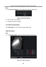
Page 50: ...erver addresses 3 Click Save to enable the settings 6 3 4 Video Display Settings Click Video Display to enter the Video Display Settings page Video Parameters Steps 1 Click Video Parameters to enter t...

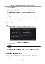
Page 51: ...luding network parameters to the factory settings Video Audio Steps 1 Click Video Audio to enter the video parameters settings page Figure 6 16 Video Audio 2 Set the parameters 3 Click Save Note It s...

Page 52: ...the actual needs 1 You can add multiple levels of organizations according to the actual needs 2 Then the added organization will be the sub organization of the upper level organization Note Up to 10...

Page 53: ...op up the adding person dialog Note The Person No will be generated automatically and is editable 2 Set basic person information 1 Enter basic information name gender tel birthday details effective pe...

Page 54: ...k Add to save the settings 6 6 2 Modify and Delete Person Select the person and click Edit to open the editing person dialog To delete the person select a person and click Delete to delete it Note If...

Page 55: ...import to the client for further operation Steps Note This function is only supported by the device the connection mothod of which is TCP IP when adding the device 1 In the organization list on the le...

Page 56: ...er the context of your task here optional Steps 1 Enter your first step here Enter the result of your step here optional Example Enter an example that illustrates the current task optional What to do...

Page 57: ...Figure 6 17 Issue Card in Batch 2 Click Settings Video Intercom Face Recognition Door Station User Manual 45...

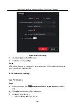
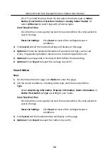
Page 58: ...ard information will display in the Person s with Card Issued list 6 6 8 Permission Settings Add Permissions Steps 1 On the main page click AccessControlInfo Access Group to enter the page 2 Click Add...

Page 59: ...ia the iVMS 4200 Client Software Note For the user with access control module permissions the user can enter the Access Control module and manage video intercom and search information You should add t...

Page 60: ...door station 6 7 2 Live View via Door Station Steps 1 On the main page of the client software click Main View to enter the Live View page 2 In the left list of the window double click the device IP or...

Page 61: ...in the Information field 6 7 4 Search Video Intercom Information Search Call Logs Steps 1 On the Video Intercom page click Call Log to enter the page Figure 6 19 Search Call Logs 2 Set the search con...

Page 62: ...ion etc 5 Optional Input keywords in the Search field to filter the desired log 6 Optional Click Export to export the call logs to your PC Search Notice Steps 1 On the Video Intercom page click Notice...

Page 63: ...UD16891B...

Reviews: