background image

DS-PR1-60 User Manual 

UM DS-PR1-60 090920NA 

42 


Summary of Contents for DS-PR1-60

Page 1: ...DS PR1 60 Security Radar User Manual...

Page 2: ...ING AMONG OTHERS DAMAGES FOR LOSS OF BUSINESS PROFITS BUSINESS INTERRUPTION OR LOSS OF DATA CORRUPTION OF SYSTEMS OR LOSS OF DOCUMENTATION WHETHER BASED ON BREACH OF CONTRACT TORT INCLUDING NEGLIGENCE...

Page 3: ...er Indicates a hazardous situation which if not avoided will or could result in death or serious injury Caution Indicates a potentially hazardous situation which if not avoided could result in equipme...

Page 4: ...ient 12 4 1 1 Add Map 12 4 1 2 Add Zones 13 4 1 3 Add Trigger Line 15 4 2 Radar Settings in the Client Software 17 4 2 1 Add Map 17 4 2 2 Add the Radar to the Map 18 4 2 3 Add Radar Zone 21 4 2 4 Add...

Page 5: ...orage Server 48 1 1 2 Set Storage Schedule via NVR 49 1 2 Set Tracking Strategy 49 Chapter 8 Alarm Settings 50 8 1 Alarm Center 50 8 2 Notification Push 50 8 3 Set Zone 51 8 4 Set Alarm Output 51 8 5...

Page 6: ...ptimum Detection Range 63 D 2 How To Solve Radar Not Shown in Device List on Radar Page 63 D 3 How To Adjust Sensitivity to Avoid False Alarms 63 D 4 How To Raise the Camera Tracking Precision 64 D 5...

Page 7: ...ter to the software Enter Device Management Device Add in the Maintenance and Management list to add the device Set the device port no as 80 The activation user name and password are used for device l...

Page 8: ...e highly recommend that you create a strong password of your own choosing using a minimum of eight characters including at least three of the following categories upper case letters lower case letters...

Page 9: ...password and confirm the password STRONG PASSWORD RECOMMENDED We highly recommend that you create a strong password of your own choosing using a minimum of eight characters including at least three o...

Page 10: ...The default IP address of the device is 192 0 0 64 2 Create and confirm the admin password STRONG PASSWORD RECOMMENDED We highly recommend that you create a strong password of your own choosing using...

Page 11: ...ation Parameters Wired Network Settings to enter thepage Figure 3 1 Wired Network Settings Page 4 Set the parameters Automatic Settings Enable DHCP and set the HTTP port Manual Settings Disabled DHCP...

Page 12: ...Configuration page for five minutes without any operation will automatically log out The Web client s Radar page cannot receive CID alarms and zone colorchanges 4 1 1 Add Map 1 Enter the radar s IP ad...

Page 13: ...the upper left corner of the map The target track will appear on the radar detection area You can draw a zone with reference to the track The track clears when disabled 5 Click Draw Zone Manually and...

Page 14: ...the targets entering the area and trigger the alarm The warning zone is orange Disabled Zone The disabled zone will block the target track into the area The disabled zone is gray 7 Click OK 8 Optiona...

Page 15: ...e You can draw Trigger Line or Dual trigger Line The alarm can be triggered by crossing the Trigger Line according to the trigger line rule the alarm can be triggered only after crossing double lines...

Page 16: ...trigger line in any direction 8 Trigger lines cannot cross each other 6 Click OK to complete the drawing 7 Optional Double click on the trigger line to enter the trigger line editingmode Figure 4 8 A...

Page 17: ...age 2 Select the radar group and click Add map to load a map Supported picture formats jpg png bmp jpeg Figure 4 11 Add a Map 3 Click OK 4 Click Edit Scale 5 Click on the map to draw a straight line s...

Page 18: ...ore they can be added to the same map 1 In the E map page click Edit in the upper right corner of the map to enter the editingmode 2 Expand the device group in the left list and then click and drag th...

Page 19: ...ing a prompt will appear There are targets in the zone enable mandatory arming and click OK to arm Disarm Close the arming mode of the radar detection area Event Search and play back alarm events For...

Page 20: ...0 Figure 4 15 Confirm Terminals 4 Click on the map to confirm the actual locations of marker 1 and marker 2 Figure 4 16 Confirm Actual Locations 5 Click OK on pop up window The system will automatical...

Page 21: ...corner of the map The target track will appear on the radar detection area You can draw a zone with reference to the track The track cleared when disabled 3 Click Radar Settings Draw Zone Manually and...

Page 22: ...will identify target that has potential risks in advance and trigger alarm but will not store alarm track The early warning zone is green Warning Zone The warning zone will identify the targets enteri...

Page 23: ...Drag aMarker 3 Drag the marker to change the shape of thezone Figure 4 22 Move the Zone 4 Hold to move the zone 5 Click outside the zone to exit the zone editing mode Todelete a zone click in the zone...

Page 24: ...es of Dual trigger Line according to the alarm rule Drawing a dual trigger line that is too tortuous will cause a failure 3 Draw the trigger line 1 Click on the radar detection area to draw a trigger...

Page 25: ...he drawing 5 Optional Click on the trigger line will appear different options Edit Delete and Move You can edit the trigger line by clicking on it Figure 4 25 Add a Marker Drag a Marker Drag a marker...

Page 26: ...r Line Delete Click to delete the trigger line 4 2 5 Other Auxiliary Functions Live View Before using this function you need to confirm that the speed dome has been calibrated and the speed dome has a...

Page 27: ...Z buttons to make sure that the reference point is displayed in the live view window Click to enable 3D location click the reference point and the point will be in the middle of the frame If the speed...

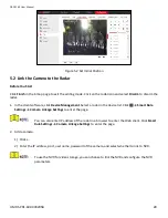
Page 28: ...vice Management Select a radar in the device list Click Smart Rule Settings Camera Linkage Settings to enter the page You can also enter IP address of the radar in a browser to enter the Web client Cl...

Page 29: ...ent 2 Click Add in the device list enter name IP address port user name password of the camera Check Import to Group 3 Click Add 5 3 Calibrate Camera Calibrate the linked camera to ensure the accuracy...

Page 30: ...ick Import 4 Click E map to enter the page and click Edit to enter the editing mode 5 Click Radar Settings Master slave Tracking Settings 6 Select a radar in the drop down list 7 Click a live view win...

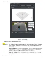
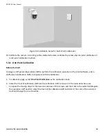
Page 31: ...r the calibration point selection One Point Calibration or Multi Point Calibration One Point Calibration Applicable to the scene where the radar and the camera are installed on the same pole or the ca...

Page 32: ...DS PR1 60 User Manual UM DS PR1 60 090920NA 32 Figure 5 5 Installation Scene for One Point Calibration...

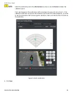
Page 33: ...alibration operation in the client software and a staff person calibration staff to cooperate with the calibration 1 In calibration page select One Point Calibration as the calibration mode 2 Select t...

Page 34: ...o adjust the altitude of the calibration staff to two thirds of the altitude of the window and click the direction buttons to align the central sign with the calibration staff for precise alignment cl...

Page 35: ...on point The track disappears if the calibration staff is standing in the place for more than 7s If the calibration staff does not move to the calibration point when the track disappears you need to a...

Page 36: ...re to select points Figure 5 9 Multipoint Distribution Instance It is required to set three calibration points equally distributed when using multipoint calibration 3 According to the calibration poin...

Page 37: ...iew window Adjustment will change the PTZ position of the current calibration point and results in an incorrect calibration You can adjust the PTZ buttons when calibrating the calibration point If you...

Page 38: ...watch point when no target appears within 10 s in the radar detection area Before You Start Add the radar to the map Link the camera to the radar and add the camera to the client software Calibate the...

Page 39: ...e watch point You can click on the screen and the screen will automatically adjust to the clicked center Operation Description Direction control Button Adjust the camera direction Hold to move the cam...

Page 40: ...ick Event Management Alarm Event to enter the page 2 Select a zone in the left list 3 Check event in the right list 4 Click Edit Linkage to edit the trigger client actions and cameras that you need to...

Page 41: ...show the alarm event list 3 Click to enable alarm triggered pop up image 4 When the alarm is triggered the client software will automatically pop up an alarm window Figure 5 13 The Alarm Window Check...

Page 42: ...DS PR1 60 User Manual UM DS PR1 60 090920NA 42...

Page 43: ...DS PR1 60 User Manual UM DS PR1 60 090920NA 43 5 Optional Click to disable alarm triggered pop upimage For more details see the iVMS 4200 Client Software User Manual...

Page 44: ...log into Radar Calibration Tool 1 Click Add Group in radar list to add a new group 2 Double click on the group to edit the group name 3 Select a group and click Add Radar 4 Enter IP address user name...

Page 45: ...ld diagram the operation staff needs to select the track of the calibration staff and click it The color of the selected track will change from red to yellow Figure 6 1 Select the Track 5 Ask the cali...

Page 46: ...here optional Before You Start Enter the prerequisites here optional Enter the context of your task here optional 1 Click on the Calibration List 2 Select a linked IPC 3 Select Multi Point Calibration...

Page 47: ...ion to calibrate the calibrationpoint 6 When the first calibration point is calibrated completely let the calibration staff move to the next calibration point after the yellow track disappears then re...

Page 48: ...setting storage schedule you can refer to User Manual of iVMS 4200 Client Software 1 In client software click Storage Schedule to enter the page 2 Select the camera in the Camera Group list Figure 7...

Page 49: ...amera Click Choose Yes in Link to NVR Enter IP address port and network camera No Click OK 1 2 Set Tracking Strategy 1 Select the radar and click in client software or enter the radar IP address in th...

Page 50: ...er to enable the center group The alarm information will be uploaded to the selected center group 3 Select Protocol Type from the drop down list select Server Address Type from the drop down list ente...

Page 51: ...will push notifications when the user operates the device 1 Click Save 8 3 Set Zone 1 Select the radar and click in the client software or enter the radar IP address in the address bar of the Web brow...

Page 52: ...elay linked zone is triggered by an alarm the relay will remain open until the target exits the zone or the alarm is manually closed After the zone tracking is turned on if only the zone is selected i...

Page 53: ...er Click Smart Rule Settings Alarm Speed Settings to enter the page 2 Check Motion Speed 3 Slide the bar to set Min Speed Threshold and Max Speed Threshold After enabled only targets that moves in set...

Page 54: ...r you need to set the main radar IPaddress You need to ensure that the port no set for the slave radar is the same as the main radar What To Do Next When the target is appear on the radar the target i...

Page 55: ...lick Save to complete 9 4 Set Frequency Range Settings 1 Select the radar and click in the client software or enter the IP address of the radar in the address bar of the web browser Click Radar Settin...

Page 56: ...earching and playing back alarm events For details see Set Record and Storage Settings 1 In the client software click E map and click Finish to exit the editingmode 2 Click on the radar icon that need...

Page 57: ...f the Web browser Click System Time to enter the page Figure 11 1 Time 2 Set the time zone and synchronization method 3 Click Save 11 2 Manage User 1 Select the radar and click in the client software...

Page 58: ...guration File to export the device configuration parameters to the PC Exporting configuration file requires a password to be used for file encryption Upgrade File Click View to select an upgrade file...

Page 59: ...Status You are able to enable LED function Select the device and click in the client software or enter the device IP address in the address bar of the web browser Click System Device Status to enter...

Page 60: ...Height Vertical Angle Far Detection Limit Near Detection Limit 1 5 m 0 59 m 1 91 m 1 5 m 3 59 2 m 1 98 m 1 5 m 6 59 4 m 1 87 m 1 5 m 9 52 m 2 3 m 2 0 m 0 59 4 m 1 8 m 2 0 m 3 59 4 m 2 19 m 2 0 m 6 59...

Page 61: ...reset button You can format the device as follows 1 Power off the radar and then hold the reset button while powering the radar on 2 Keep holding until the red and green LED flashes six times then rel...

Page 62: ...ator status description of the radar Table C 1 Indicator Description Indicator Status Solid Green Radar powered on Solid Red Zone alarm occurred Flashing Red and Green Radar Network Disconnection Rada...

Page 63: ...last tester distance that displayed by OSD is the far detection distance When testing the far detection distance the tester is required to move along the center normal of the detection area to ensure...

Page 64: ...How to Solve No Reference Point on Frame While Setting Speed Dome Initial Position If the speed dome is tilted it may cause the reference point to be above the center of the frame or outside the fram...

Page 65: ...reset the speed dome initial position after the maximum elevation angle adjustment D 6 What Is the Reason that Failed to Draw a Zone Automatically The main reason is that the moving target with track...

Page 66: ...the glasses are flat and the reflection is concentrated there may be a false alarm when there are glasses in the radar scene The higher the sensitivity the more probability a false alarm will be trigg...

Page 67: ...rix Device Command Scan the following QR code to get the device common serial port commands Note that the command list contains all commonly used serial ports commands for all Hikvision security contr...

Page 68: ...device Server IP The server IP is used to support network service communication For example the NTP server can be used to perform timing on the radar device Control port For details please refer to Co...

Page 69: ...DS PR1 60 User Manual UM DS PR1 60 090920NA 69...

Page 70: ...DS PR1 60 User Manual UM DS PR1 60 090920NA 70...

Page 71: ...DS PR1 60 User Manual UM DS PR1 60 090920NA 71 UD13649B...

Reviews: