


ECI-B64Z2 Quick Start Guide
QSG ECI-B64Z2 041018NA
3
Drill Template
Drill Template
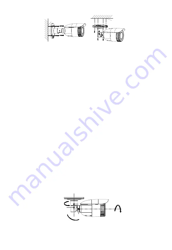
Secure the Camera
Figure 2-6
Note:
●
The supplied screw package contains self-tapping screws and expansion bolts.
●
For a cement wall (or ceiling), use expansion bolts to secure the camera. For a
wooden wall (or ceiling), use self-tapping screws.
6.
Connect the corresponding cables, such as the power cord or network cable.
7.
Power on the camera, and set the network configuration (for further detail, refer to the
Network Camera LAN Configuration
and
Access via Web Browser
sections) to check
whether the image is at an optimum angle. If not, adjust the surveillance angle.
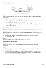
Pan Adjustment
Steps:
1).
Loosen lock screw 1.
2).
Adjust the panning position of the camera. The adjusting range is from 0° to 360°.
3).
Tighten lock screw 1.
Tilt Adjustment
Steps:
1).
Loosen lock screw 2.
2).
Adjust the tilting position of the camera. The adjustment range is from 0° to 90°.
3).
Tighten lock screw 2.
Rotation Adjustment
Steps:
1).
Loosen lock screw 3.
2).
Rotate the rotation position to adjust the azimuth angle of the image. The adjusting
range is from 0° to 360°.
3).
Tighten lock screw 3.
Pan: 0° to 360°
1
2
3
Rotation
0° to 360°
Tilt: 0° to 90°
1 Lock Screw 1
2 Lock Screw 2
3 Lock Screw 3
View Angle Adjustment
Figure 2-7


