background image

Sliding gate opener SLG5280X user manual(SL0720) 


Figure 5: Turn on 90

°


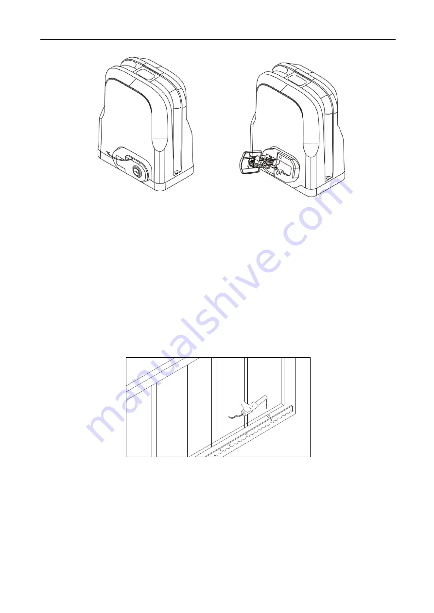
4.3.3 Gear rack installation 

  Fix the mounting screws to the rack. 

  Put the rack on the output gear, and weld the mounting screw to the gate (each screw with one 

solder joints firstly). 

  Unlock the motor and can pull the gate smoothly. 

  Please check whether there is a fit clearance between rack and output gear, as shown in Figure 

7. 

  Weld all the mounting screws to the gate firmly. 

  Make sure that all racks on the same straight line.   

  Pull the gate after installed, make sure the entire trip is flexible no stuck. 


Figure 6 


The fit clearance of output gear and rack is shown in Figure 7 below: 


Summary of Contents for SLG5280X

Page 1: ...Sliding gate opener SLG5280X user manual SL0720 1 Sliding Gate Opener SLG5280X User Manual With control board SL0720...

Page 2: ...a single button mode or three button mode please refer to the instructions of the remote control in accordance with the actual gate opener type The indicator light on the remote control unit will flic...

Page 3: ...l already choose Remote control 2 4 Spring limit switch accessories box Magnetic limit switch accessories box 1 4 1 or Spring limit switch block Magnetic limit switch block 1 4 2 Outer hexagonal bolt...

Page 4: ...lamp different models are optional 1pc 5 Photocell different models are optional 1pair 6 Mounting plate 1piece 3 Technical parameters Model SLG52801 SLG52802 SLG52803 SLG52804 Power supply 110VAC 50Hz...

Page 5: ...put torque 14N m 14N m 14N m 14N m Output shaft height 46mm 46mm 46mm 46mm Frequency 433 92 MHz 433 92 MHz 433 92 MHz 433 92 MHz Working temperature 20 C 70 C 20 C 70 C 20 C 70 C 20 C 70 C Package wei...

Page 6: ...ack Remote control 4 2 Size of main engine and accessories 4 2 1 Size of main engine Figure 2 4 2 2 Size of mounting plate 107 150 204 0 3 90 0 3 8 10 Figure 3 4 3 Installation procedures 4 3 1 Prepar...

Page 7: ...etween the gate and gate opener is suitable before casting the pedestal Embedded screws Figure 4 4 3 2 Main engine installation a Dismantle the plastic housing on the main engine before installation a...

Page 8: ...one solder joints firstly Unlock the motor and can pull the gate smoothly Please check whether there is a fit clearance between rack and output gear as shown in Figure 7 Weld all the mounting screws t...

Page 9: ...l properties and the gate can operate flexibly when moved by hands before installing the main engine In this product one control can drive one main engine only otherwise the control system will be dam...

Page 10: ...Sliding gate opener SLG5280X user manual SL0720 10 Figure 8 The installation of spring limit switch stop block is shown in Figure 9 M6 10 M6 10 M6 10 M6 10 Figure 9...

Page 11: ...t switch is shown in Figure 10 Figure 10 The installation of magnetic limit switch block is shown in Figure 11 M6 18 M6 18 M6 18 M6 18 Left side mounting Right side mounting Figure 11 Note The default...

Page 12: ...connect the wires according to the following figure user just connects the interfaces of AC input flash lamp external control switch photocell and 24VAC output then install the top cover again after...

Page 13: ...off when limit device touches limit switch Limit switch is NC 6 3 Resistance adjustment Adjust potentiometer P Open P Close to change the opening closing resistance Resistance increases when adjust i...

Page 14: ...on is not effective any more when a new button has been learned in the same transmitter For example button 1 was learned firstly button 2 or 3 has been learned of the same transmitter afterwards then...

Page 15: ...the DL2 LED lamp light as normal Remote control problem 1 remote control is not learned 2 remote control battery is low remote control battery life 6 12 months depending on frequency of use 1 learn re...

Reviews: