C
ASE
C
ONNECTIONS
REFRIGERATION
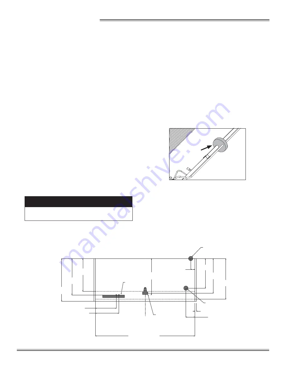
As the diagram below indicates, the coil outlet hole is
positioned forward on the right-hand side of the case, fully
visible in front of the fan plenum.
The expansion valve and other controls - located on the
left-hand side of the case - are accessible without lifting the
fan plenum and may be reached by lifting the deck pans.
If it becomes necessary to penetrate the case bottom, be
certain to seal it afterwards with canned-foam sealant and
white RTV.
PLUMBING
The drain outlet is specially molded out of PVC material
and is located in the center of the case for convenient ac-
cess. The “P” trap, furnished with the case, is constructed
of schedule 40 PVC pipe. Care should be given to ensure
that all connections are water-tight and sealed with the ap-
propriate PVC or ABS cement.
The drain lines can be run left or right of the tee with the
proper pitch to satisfy local drainage requirements. Since
the kickplate is shipped loose with the case, you should
have open access to the drain line area during installation.
35 1/16 in
[89.1 cm]
**
39 3/8 in
[99.9 cm]
41 5/16 in
[104.9 cm]
31 11/16 in
[80.5 cm]
FRONT OF CASE
C
L
1 1/2 in [3.8 cm] {END}
96 in [243.8 cm] (8' CASE)
8 11/16 in [22.1 cm]
4 in[10.2 cm]
28 5/8 in
[72.7 cm]
REFRIGERATION
REAR REFRIGERATION
(11 3/4" OFF OF FLOOR)
22 9/16 in [57.3 cm]
20 1/16 in [51.0 cm]
35 3/16 in
[89.4 cm]
JUNCTION BOX
(STANDARD)
ELECTRICAL
1 1/2" PVC DRAIN
CONNECTION
33 9/16 in
[85.3 cm]
MODEL
UPL-NRG
REMOVE THE SHIPPING BLOCKS THAT PROTECT THE
REFRIGERATION LINES DURING SHIPMENT BEFORE
OPERATING THE CASE.
REMOVE
If the kickplate has been installed, you will
fi
nd it very easy
to remove. Simply lift the kickplate up from the "J" rail and
pull it out, away from the case. See the Trim Out section
on page 6.
ELECTRICAL
Electrical hookups are made to a junction box located at
the bottom-left-front of the case.
For case-to-case wiring, run conduit between the junction
boxes. When connecting to the junction box on the bottom-
left side of the case,
fi
eld wiring should exit box from the
right side (furthest away from case wiring) to allow more
room inside for wiring connections.
C A U T I O N
If any brazing is necessary, place wet rags
around the area to avoid tank damage.
▲
7
Summary of Contents for UPL-NRG
Page 2: ...ii...
Page 15: ...APPENDIX A WIRING DIAGRAMS...
Page 16: ......
Page 17: ...NOTES...
Page 18: ...NOTES...


