background image

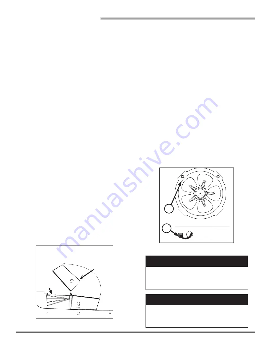
SINGLE PIECE FAN PLENUM LIFT UP

PLENUM
COVER

COIL
COVER

SINGLE PIECE FAN 
PLENUM  SWINGS UP 
FOR EASY CLEANING

U

SE

 & M

AINTENANCE

CLEANING PROCEDURES

• 

A periodic cleaning schedule should be established to 
maintain proper sanitation, insure maximum operating 
efficiency,  and avoid the corrosive action of food fluids 
on metal parts that are left on for long periods of time.  
We recommend cleaning once a week.

• 

To avoid shock hazard, be sure all electrical power is 
turned off before cleaning.  In some installations, more 
than one disconnect switch may have to be turned off to 
completely de-energize the case.

• 

All surfaces pitch downward to a deep-drawn drain 
trough, funneling liquids/ to the front of the case where 
the waste outlet is located for easy access.  Check 
waste outlet to insure it is not clogged before starting 
the cleaning process and avoid introducing water faster 
than the  case drain can carry it away.

• 

The coil is covered to keep food fluids from entering 
but is easily accessible when coil cleaning is required. 
Simply remove the screws; lift and remove the plenum 
cover; then lift and remove the coil cover. Be certain that 
both the plenum and coil cover are properly closed and 
secured after cleaning to avoid air leaks.

• 

If any potentially harmful cleaners are used, be certain 
to provide a temporary separator (e.g., cardboard, plas-
tic rap, etc.) between those cases that are being cleaned 
and those that may still contain product.

• 

Avoid spraying cleaning solutions directly on electrical 
connections.

• 

Allow cases to be turned off long enough to clean any 
frost or ice from coil and pans.

• 

Remove kickplate and clean underneath the case with a 
broom and a long-handled mop.  Use warm water and a 
disinfecting cleaning solution when cleaning underneath 
the cases. 


D A N G E R

SHOCK HAZARD

Always disconnect power to case when servic-

ing or cleaning.  Failure to do so may result in 

serious injury or death.


W A R N I N G

Exercise extreme caution when working in a 

case with the coil cover removed.  The coil 

contains many sharp edges that can result in 

severe cuts to the hands and arms.

FANS

The evaporator fans are equipped with 16-watt fan motors.  
Motors have a counter-clockwise rotation when viewed 
from the shaft end.  

The fan blades are 8” in diameter with a 20

o

 fan blade 

pitch.  It is important that the blade pitch be maintained as 
installed.  

Do not attempt a field modification by alter-

ing the blades.

Fan motors may be changed with an easy two-step pro-
cess without lifting up the plenum, thereby avoiding the 
necessity to unload the entire product display to make a 
change:

1.  Unplug the fan motor, easily accessible outside the  

plenum.  Push power cord back through plenum 
opening.

2.  Remove two fasteners, then lift out the entire fan 

basket.

Reverse procedure when re-installing fan basket.

FAN ASSEMBLY

1

2

9

Summary of Contents for UPL-NRG

Page 1: ...rgy Data 2 Case Dimensions 3 General Information 4 Installation 5 6 Case Connections 7 Airflow Defrost Temp Control 8 Use Maintenance 9 Parts Ordering 10 Appendix A Wiring Diagrams Installation Operat...

Page 2: ...ii...

Page 3: ...installation and operations handbooks accompanied by an alert symbol paired with the word DANGER WARNING or CAUTION All warning messages will inform you of the potential hazard how to reduce the risk...

Page 4: ...ding without limita tion to the display itself to the location where the display is situated e g store and to any surrounding property DO NOT use misting systems water hoses or other devices that spra...

Page 5: ...g protected When de energizing refrigeration units containing R 744 CO2 venting of the R 744 CO2 refrigerant may occur through the pressure regulating relief valves These valves are located on the ref...

Page 6: ...Control Settings Model 2 BTUH ft Superheat Set Point Bulb oF Evaporator oF Discharge Air oF Return Air oF Discharge 3 Air Velocity FPM UPL NRG 500 6 8 26 30 40 250 Model Defrosts per Day Electric Defr...

Page 7: ...L 1 1 2 in 3 8 cm END 96 in 243 8 cm 8 CASE 35 7 16 in 90 0 cm 46 7 16 in 117 9 cm 48 7 16 in 123 1 cm 8 5 8 in 21 9 cm 33 1 4 in 84 4 cm 25 1 16 in 63 6 cm 8 in 20 3 cm 3 13 16 in 9 7 cm 22 11 16 in...

Page 8: ...in the event of shipping damage and or shortages please contact the Service Parts Department at the toll free number listed below CASE DAMAGE Claims for obvious damage must be 1 noted on either the f...

Page 9: ...orse positions along the chalk line Spot properly leveled shim packs at each basehorse loca tion Fig 1 Caster assembly CASTER WA R N I N G Be certain that your hands and feet are out of the way before...

Page 10: ...rail with the supplied screws Fig 4 6 Insert top of kickplate into the kickplate retainer Slide the kickplate up into the retainer then down onto the J rail Fig 4 Be certain that the bottom of the ki...

Page 11: ...the drain line area during installation 35 1 16 in 89 1 cm 39 3 8 in 99 9 cm 41 5 16 in 104 9 cm 31 11 16 in 80 5 cm FRONT OF CASE C L 1 1 2 in 3 8 cm END 96 in 243 8 cm 8 CASE 8 11 16 in 22 1 cm 4 i...

Page 12: ...below It is important that you do not overload the food product dis play so that it impinges on the air flow pattern Overloading will cause malfunction and the loss of proper temperature levels partic...

Page 13: ...rary separator e g cardboard plas tic rap etc between those cases that are being cleaned and those that may still contain product Avoid spraying cleaning solutions directly on electrical connections A...

Page 14: ...part is intended Length of the part if applicable Color of part if painted or color of polymer part Whether part is for left or right hand application Quantity Serial plate is located on the back of...

Page 15: ...APPENDIX A WIRING DIAGRAMS...

Page 16: ......

Page 17: ...NOTES...

Page 18: ...NOTES...

Page 19: ...ales tax or upgrading 5 When the operation is impaired due to improper installation 6 When installation and startup forms are not properly complete or returned within two weeks after startup THIS PLAN...

Page 20: ...er directly on fan motors or any electrical connections All lighting receptacles must be dried off prior to inser tion and re energizing the lighting circuit Please refer to the Use and Maintenance se...

Reviews: