


Specifications
Chapter 1: Introduction
Page 1 - 8
TRANS
l
LIFT
TM
Resident Stand Assist Service Manual (man173)
1
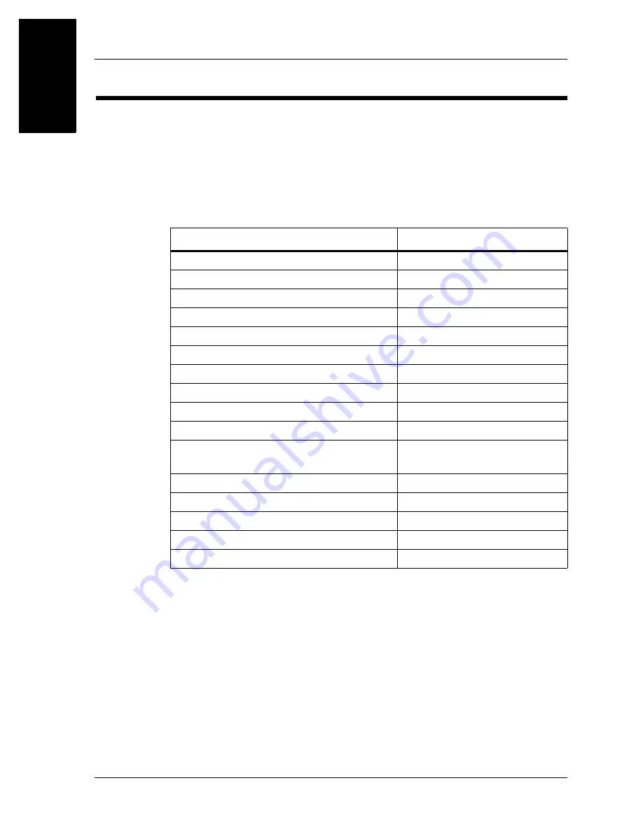
Specifications
Physical Description
See table 1-1 on page 1-8 for TRANS•LIFT
TM
Resident Stand Assist
specifications.
Table 1-1. Specifications
Feature
Dimension
Height (fully extended)
63.625" (161.61 cm)
Width
24" (61 cm)
Length
52" (132 cm)
Weight
117 lb (53.12 kg)
Caster size
3" (8 cm)
Floor to Base Clearance
4.625" (11.75 cm)
Maximum angle of inclination (up)
70°
Maximum angle of inclination (down)
14°
Minimum wall clearance
15" (38 cm)
Maximum resident weight
400 lb (181 kg)
Lift range
Floor level 0" (0 cm) to 40"
(102 cm)
Storage relative humidity range
20 - 95%
Operating relative humidity
30 - 85%
Storage temperature range
-40°F - 150°F (-41°C - 65.5°C)
Ambient operating temperature range
50°F - 110°F (10°C - 43°C)
Sound level
<45 dBA at resident’s ear


