TRIM OUT
1.
Seal the case-to-case joints with caulk (supplied), then
apply acrylic tape (supplied) over the pipe-chase seam
(Fig. 3). The tape acts as a watershed preventing wa-
ter from settling in the case joint.
5.
Loosen the cornice joint at case end (cornice screws
are located on top of the case). Be certain that cornice
joints and pins are properly aligned. Cases are now
ready to be joined.
6.
Push the cases tightly together, then lightly bolt them
together through the holes that are provided (Fig. 2).
Tighten all the joining bolts until all margins are equal.
Be careful not to over tighten.
7.
Repeat steps 2-6 of this sequence for all remaining
cases. Be certain to properly level all cases.
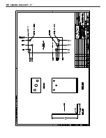
8. If seismic brackets are included, see
Appendix D
for
detailed installation instructions.
CASE INSTALLATION
2.
Re-install shelves. Be aware that differing shelf con-
figurations will affect energy consumption and case
performance.
3.
Tighten all cornice joints as needed (Fig. 4). Working
outward from the center of the line-up, loosen the fas-
teners on the top and slide the cornices in one direction
so that each joint aligns tightly together. Tighten the
fasteners on top and apply an external joint band on
the extreme ends of the lineup if a gap exists.
4.
Properly align the front panels as needed, then install
the front panel trim (supplied).
5.
Attach the one-piece kick plate to the factory installed
kickplate retainers with the screws provided.
Fig. 3 Sealing the pipe chase
ACRYLIC
TAPE
PIPE
CHASE
ATTENTION!
Installation of 3rd-party materials may
result in diminished case performance.
Fig. 4 Cornice joints
CORNICE
ALIGNMENT
PIN
CORNICE
JOINT
4
Summary of Contents for 3NDML-NRG
Page 16: ...BLUE WHITE BLACK 3NDML WIRING DIAGRAM B2 ...
Page 19: ...SEISMIC BRACKET 5 D2 ...
Page 20: ...SEISMIC BRACKET 7 D3 ...
Page 21: ...SEISMIC BRACKET 11 D4 ...
Page 22: ...SEISMIC BRACKET 15 D5 ...


