7
CASE INSTALLATION
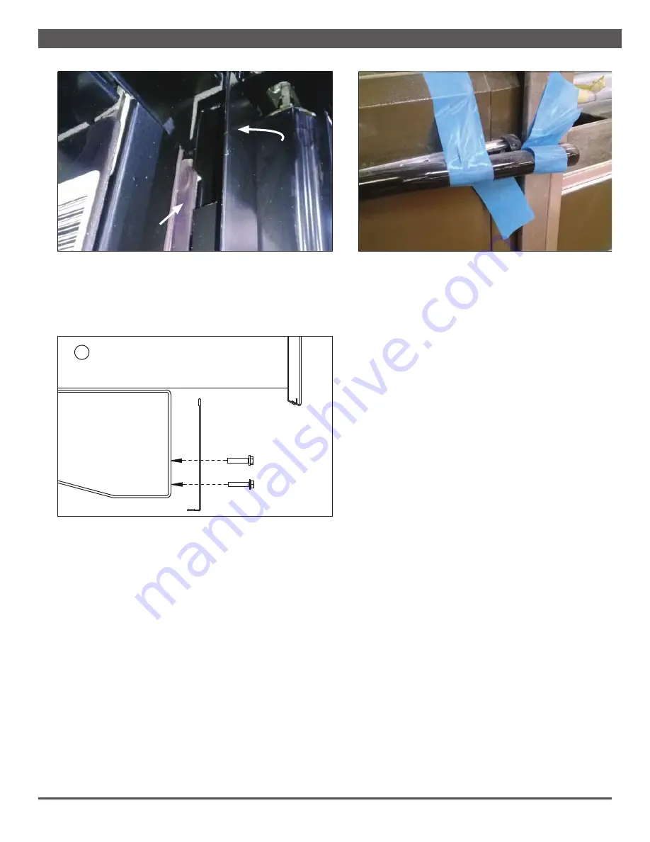
Fig. 8 Attach kickplate with supplied screws
KICKPLATE
KICKPLATE
RETAINER
SCREWS
Fig. 7 T-Bar case frame joint trim seals case frame gap
T-BAR
T-BAR
CASE FRAME
CASE FRAME
JOINT
JOINT
FRAME
FRAME
GAP
GAP
7.
Install the front kickplate (Fig. 8) to the kickplate re-
tainer as shown. Install the end kickplates with screws
provided and insert the plug buttons.
8.
Install the case top fascia (if included). See
Appendix
D
for installation instructions.
9.
Install electric display modules (if included). See
Ap-
pendix E
for installation instructions.
10.
If the case is outfi tted with a factory-installed, snap-on
bumper track, install the snap-on track bumper onto
the track, up to 96 feet. For rigid bumper, cut for as
tight a fi t as possible–to allow for minor shrinkage fol-
lowing start-up–and install. For rolled bumper, Hill-
phoenix recommends leaving an additional 6 inches of
nose bumper at the ends to allow for shrinkage during
the fi rst 24–48 hours following case start-up (Fig. 9).
11.
After suffi cient time has passed, cut away the excess
bumper for fi nal fi t and fi nish. Be certain to use an ap-
propriate cutting tool (tubing- or PVC-cutter) to ensure
a smooth cut.
Fig. 9 Leave 6 inches of extra bumper
Summary of Contents for VNRB
Page 2: ...ii ...
Page 5: ...v Revision History new manual format_9 19 ...
Page 51: ...H2 SEISMIC BRACKETS 4 BRACKETS ...
Page 52: ......


