4
Assembly
Arm and Stay Assembly
1.
Fit top cap lower assembly
792
to secondary
standard assembly
795
and fasten securely
with screw
204
and nut
409
(
Fig. 5
).
2.
Locate arm stay bracket
787
onto the arm
793
and align the mount holes.
Ensure the bracket is assembled as per
Fig 6
(with staples up).
3.
Squeeze the arm stay bracket
787
together
and fasten securely with screws
181
and nuts
434
(
Fig. 6
).
4.
Fit tube stays
794
to arm stay brackets
787
and fasten securely with screws
201
and
nuts
447
(
Fig. 6
).
5.
Place the arms into the cross and assemble
the tube stay into the top cap assembly
791
and
792
with the screw
203
.
Note:
Do not fit the nut yet.
6.
Repeat step 5 for the other three arms.
For Model 4 fit nuts
409
to screws
203
now.
For Model 5 refer to step 7.
7.
For Model 5, hook the inner rod stays
789
into the innermost staples on the arms.
Position other end underneath the top cap
lower assembly
792
and onto screw
203
.
Fit nuts
409
and tighten.
8.
Fit end caps
752
to the end of each arm.
Secondary Standard Assembly
1.
Remove the wind brake and plastic ring
ring from the top of the Main Standard
assembly by loosening the securing screw.
2.
Insert secondary standard
795
into top of
main standard.
3.
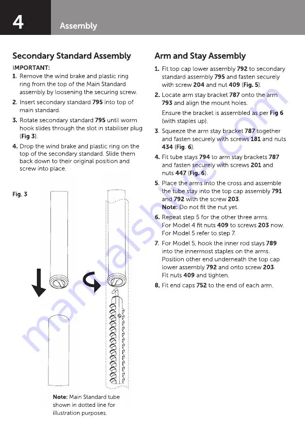
Rotate secondary standard
795
until worm
hook slides through the slot in stabiliser plug
(
Fig 3
).
4.
Drop the wind brake and plastic ring on the
top of the secondary standard. Slide them
back down to their original position and
screw into place.
Fig. 3
Note:
Main Standard tube
shown in dotted line for
illustration purposes.
IMPORTANT:


