Examine all packaging material for small parts that may have come loose during shipment. Periodic checks are recommended to insure that all
components are in proper position, tight and free from damage. Keep this assembly instruction for future reference. Adult assembly is required.
The product of Hillsdale Furniture, LLC is designed for residential use only. Customer Service Phone Number: 502-562-0000
Date: 05-12-2014
Page 1 of 1
MAYFIELD KING BED SET
Model #1259-650 Footboard & Rails
CARE & MAINTENANCE:
The touch of a soft cloth is all the maintenance the finish will ever need. Please do not use harsh or abrasive cleaners for polishing,
as they may cause damage to the finish. Periodic checks are recommended to make sure that all hardware is securely tightened.
P
P
P
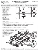
HARDWARE LIST
A (4) M6 Spring Washers
B (4) M6 Flat Washers
C (4) M6 x 90 Bolts
D (4) M8 x 50 Bolts
E (8) M8 x 30 Bolts
F (8) 4 x 30 Screws
G (8) Adjustable Feet
H (1) Ø4 Allen Wrench
I (1) Ø5 Allen Wrench
J (4) M8 Flat Washers
K (4) M8 Spring Washers
PARTS LIST
L (1) Footboard
M (2) Feet
N (2) Side Rails
O (4) Support Beams
P (4) Support Legs
QTY
PART
8
E
8
G
HARDWARE
QTY
PART
HARDWARE
8
1
F
H
1
I
4
A
4
C
4
4
B
D
FF
N
N
O
O
O
O
O
FIGURE 5
FIGURE 1
D
D
L
N
L
4
K
4
J
C
C
A
A
B
B
M
FIGURE 2
JJ
K
K
EE
G
N
O
P
P
FIGURE 3
FIGURE 4
P
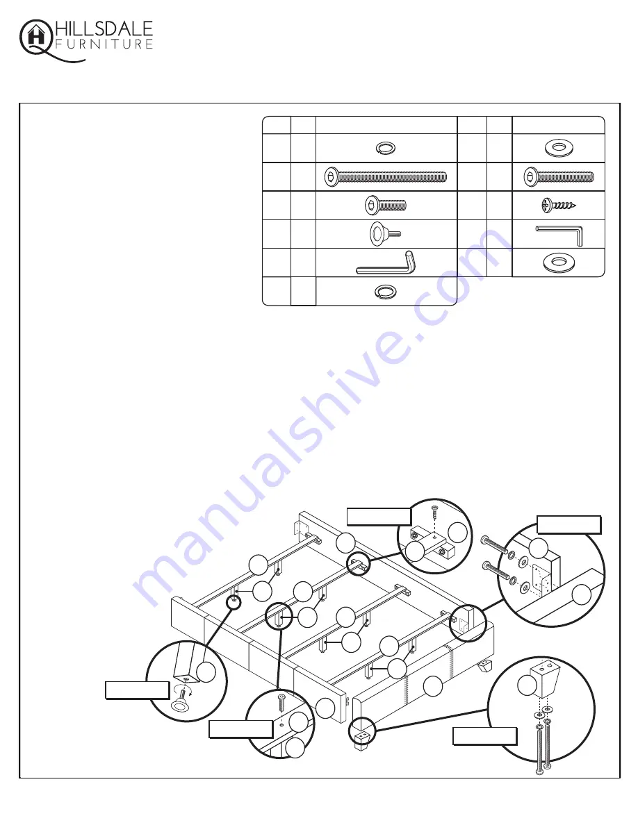
STEP 1 - Figure 1
Attach Feet (M) to Footboard (L) with 2 Bolts (C), 2 Spring Washers (A) and 2 Flat Washers (B) per foot.
Tighten Bolts with Allen Wrench (H) provided.
STEP 2 - Figure 2
Attach Footboard (L) to Side Rails (N) using 2 Bolts (D), 2 Spring Washers (K) and 2 Flat Washers (J)
into each side. Tighten with Allen Wrench (I) provided.
STEP 3 - Figure 3
Attach the Adjustable Feet (G) to the Support Legs (P) by screwing them into place.
STEP 4 - Figure 4
Attach Support Legs (P) to Support Beams (O) using 1 Bolt (E) per leg. Tighten all bolts with
Allen Wrench (I) provided.
STEP 5 - Figure 5
Attach Support Beams (O) to Side
Rails (N) using 2 Wood Screws
(F) per beam. Tighten with
philips head screwdriver
(not included).


