background image


OMHAC415-100  

MAINTENANCE   PROCEDURES  


The   load   bank   should   not   require   any   special   maintenance,   however   as   with   any  
electrical   equipment   periodic   checks   should   be   carried   out   to   ensure   the   equipment  
is   in   a   safe   and   satisfactory   condition.  
 
The   following   periodic   checks   are   recommended   on   the   load   bank;  

Check   the   inlet   and   outlet   grills   are   free   from   obstruction.  
Check   the   controls   and   connection   points   are   undamaged.  
Check   connection   cables   are   undamaged.  
Check   the   fan   rotates   freely   without   obstruction. 


FAULT   FINDING   PROCEDURES  


The   following   fault   finding   procedure   is   intended   to   identify   simple   operational   errors  
and   has   been   categorised   into   two   possible   problem   areas   as   follows;  
 

FAN   COOLING   NOT   OPERATIONAL  

Check   the   power   source   is   available.  
Check   the   phase   rotation   is   correct.  
Check   the   interconnecting   cable   connections.  
Check   the   fan   motor   operates.  
Check   for   air   blockage.  
Check   fan   blades   are   secured   to   the   motor   shaft.  


LOAD   BANK   DOES   NOT   PROVIDE   SUFFICIENT   LOAD   CURRENT  

Check   the   power   source   is   at   the   required   voltage.  
Do   not   exceed   the   maximum   rating   of   the   load   bank.   

 
Any   faults   not   corrected   by   carrying   out   the   above   procedures   may   require   the  
internal   wiring   or   components   of   the   load   bank   to   be   inspected   for   damage.  
 
Note:  Isolate   the   load   bank   from   all   sources   of   power   before   removing   any  

covers.   


Testing   the   load   bank   with   the   covers   removed   should   not   be   carried   out  
as   it   presents   a   risk   of   injury   or   death   by   electric   shock.  


Repair   or   replacement   should   be   carried   out   by   the   manufacturer. 


11  


Summary of Contents for HAC240

Page 1: ...OPERATING MANUAL for AC LOAD BANK type HAC240 415 100 iHHC3 hand held controller single three phase operation 50 Hz issue 3 ...

Page 2: ...NCE PROCEDURES 11 FAULT FINDING PROCEDURES 11 FAN COOLING NOT OPERATIONAL 11 LOAD BANK DOES NOT PROVIDE SUFFICIENT LOAD CURRENT 11 The information contained in this document is considered correct at the time of printing and given in good faith Hillstone Products bears no responsibility for the accuracy of the data given or any responsibility resulting from the use of the equipment Unit 1 2 Freetow...

Page 3: ...es The unit comprises of pre set force cooled high powered resistor channels which allows manual adjustment of the load current via a hand held controller Safety features include internal fuse protection fan motor overload protection auxiliary circuit protection auto shutoff in the event of a mains interruption The load bank is force cooled by a single phase powered fan which is connected to the l...

Page 4: ...the air exhaust During operation the load bank should not be covered or positioned to restrict air flow Caution some metal surfaces will be hot during operation At the end of any test the fan should be kept running for 10 minutes without load to remove the residual heat from the load bank case CONNECTION PROCEDURE Ensure the power source to be tested is compatible with the load bank operating volt...

Page 5: ...OMHAC415 100 CONNECTION DIAGRAM FOR 3PHASE TEST 5 ...

Page 6: ...OMHAC415 100 SINGLE PHASE CONNECTION up to 33kW 6 ...

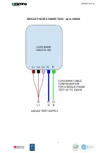
Page 7: ...OMHAC415 100 SINGLE PHASE CONNECTION up to 100kW 7 ...

Page 8: ...ower source from the UPS or generator 4 Switch on the green panel mounted rocker switch 5 Ensure the fan rotates in the correct direction with exhaust air being expelled from the exhaust grill 6 Do not exceed the maximum rating of the load bank 7 At the end of a test the mains control rocker switch should be left on for a few minutes until the resistors have cooled 8 Ensure the power source is iso...

Page 9: ...he black buttons to increase and decrease the load in 1kW steps for each button press 5 New load profiles can be set by pressing the X1 X10 or X100 push buttons and accepting or reverting yellow button back to the existing load 6 The load can be disconnected from the power source in two ways a SLOW STOP orange push button this feature removes the total load in sequence in a few seconds b QUICK STO...

Page 10: ...kgs approx Movement 5 swivel castors Load Bank Environmental Designed for outdoor operation Electrical control chamber IP54 Element chamber IP21 TYPICAL PERFORMANCE TABLE RATING TABLE Internal Channels 415VAC 240VAC L1 L2 L3 Linked 240VAC L1 only Channel Watts Channel Current Channel Watts Channel Current Channel Watts Channel Current 1 1 000 W 1 4 A 1 000 W 4 17 A 333 W 1 4 A 2 1 000 W 1 4 A 1 00...

Page 11: ...ible problem areas as follows FAN COOLING NOT OPERATIONAL Check the power source is available Check the phase rotation is correct Check the interconnecting cable connections Check the fan motor operates Check for air blockage Check fan blades are secured to the motor shaft LOAD BANK DOES NOT PROVIDE SUFFICIENT LOAD CURRENT Check the power source is at the required voltage Do not exceed the maximum...

Reviews: