background image


OMHAC415-120PX 


SPECIFICATION  

Type   ref 

HAC415-120PX 


Max   operating   voltage 

415V   three   phase 


Max   current   rating 

171A   per   phase 


Max   power   rating 

123   KW   three   phase 


Operating   Frequency 

50   Hertz 


Connection 

star   4   wire,   balanced   load 


Controller 

HHC 


Resistor   tolerance 

+/-7.5% 


Operating   ambient  temperature 

0   to   +35   deg   C 


Storage   ambient   temperature 

-10   to   +45   deg   C 


Master   PCB 

n/a 


Relay   PCB 

HP-FETDRV-2-ISS2 


PSU   PCB 

n/a 


Data   Log   PCB 

n/a 


Operating   ambient  temperature 

0   to   +40   deg   C 


Storage   ambient   temperature 

0   to   +80   deg   C 


Lifting 

Fork   Lift   Pockets 


Load   bank   dimensions 

Length 

1140mm  


Width 

580mm  


Height 

1130mm 


Weight 

145kgs 


RATING   TABLE   

HAC415-120PX         Approximate   Available   current   &   power   at   415V   50Hz 


Channel 


Approx   amps   @  


400V   3ph 


Approx   watts   @  


400V   3ph 


Fan 


1.6A 


600W 


16.7A 


12000W 


29.2A 


21000W 


62.5A 


45000W 


62.5A 


45000W 


Total 


171A 


123000W 


9  


Summary of Contents for HAC415-120PX

Page 1: ...OMHAC415 120PX OPERATING MANUAL for AC LOAD BANK type HAC415 120PX issue 1 Serial No M37091 1...

Page 2: ...he information contained in this document is considered correct at the time of printing and given in good faith Hillstone Products bears no responsibility for the accuracy of the data given or any res...

Page 3: ...controller The load bank is force cooled by a three phase powered cooling fan which together with the controls are supplied from the test source Safety features include internal fuse protection fan m...

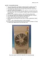
Page 4: ...possibility of electric shock 4 When in use the load bank should be cordoned off using safety barriers 5 The load bank should only be operated in an area with adequate ventilation 6 Care should be tak...

Page 5: ...aximum operating voltage D Check all panel mounted ON OFF switches are in the OFF position E Connect the handheld controller to the load bank via the CAN socket F If multiple load banks are to be used...

Page 6: ...colour coding required for load bank connections H An undrilled gland plate is provided at the front of the load bank for cable entry I Connect all test cables to the load bank see fig 5 J The load co...

Page 7: ...Ensure the fan rotates in the correct direction with exhaust air being expelled from the exhaust grill there is also an indication arrow positioned above the fan which shows the direction the blades s...

Page 8: ...ach press of the UP button will increase the load of each load bank by approximately 12kW up to a maximum of 120kW 3 By pressing the DOWN button the load will decrease on each load bank by approximate...

Page 9: ...ambient temperature 10 to 45 deg C Master PCB n a Relay PCB HP FETDRV 2 ISS2 PSU PCB n a Data Log PCB n a Operating ambient temperature 0 to 40 deg C Storage ambient temperature 0 to 80 deg C Lifting...

Page 10: ...lem areas as follows FAN COOLING NOT OPERATIONAL Check the power source is available Check the interconnecting cable connections Check the fan is running in the correct direction Check the fan motor o...

Page 11: ...tity supplied 1 Date of manufacture 7th July Note This document certifies that the whole of the items detailed above have been manufactured tested and inspected and unless otherwise stated conform in...

Reviews: