


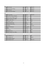

The brush motor doesn’t work properly
1.
(BASE) The brush motor is Off
⇒
Activate the brush motor by lowering the lever.
2.
(PLUS) The brush motor is Off
⇒
Activate the brush motor with the Wash mode.
3.
The brush motor is not powered properly
⇒
Check the power connections on the brush mo-
tor.
4.
The display shows an alarm message
⇒
Check what alarm message is shown and solve
the related issue by following the proper instruc-
tions
(see section
at page
.
5.
(BASE) The microswitch on the brushdeck lever
doesn’t work
⇒
Replace the microswitch.
6.
The carbon brushes are worn out
⇒
Replace the carbon brushes
(see section
??
at page
??
)
.
7.
(BASE) The brush motor is not powered even if
the microswitches are working properly
⇒
Verify the electrical wiring and proper operation
of the Main Board and replace it if necessary
(see
section
??
at page
??
)
.
8.
The brush motor is not working even if powered
⇒
Check the Float and Recovery Tank and if full
drain it completely.
If the problem persists replace the motor
(see sec-
tion
??
at page
??
)
.
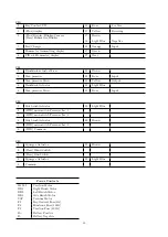
The Brushdeck doesn’t move
1.
(BASE) The brush deck Lever doesn’t move
⇒
Check that there are no mechanical obstacles to
the movement of the lever.
2.
(BASE) The lever moves but the brush deck
doesn’t move
⇒
Check the microswitch, the actuator and its con-
nections.
3.
The display shows an alarm message
⇒
Check what alarm message is shown and solve
the related issue by following the proper instruc-
tions
(see section
at page
.
4.
The brush deck is lowered but it doesn’t touch
the ground
⇒
Check the settings of the actuator.
5.
The brush deck does not lift properly
⇒
Check the adjustments of the actuator.
6.
The brush deck does not move
⇒
Verify the actuator connections to the main
board and the max pressure microswitch.
19
Summary of Contents for 108538
Page 1: ...SERVICE MANUAL TRIDENT R30SC R28SC Version AA Date August 5 2019 Document Number 100x...
Page 4: ...Part I Product Introduction 4...
Page 10: ...1 6 Machine Dimensions 1 6 1 R30SC 10...
Page 11: ...1 6 2 R28SC 11...
Page 15: ...Part II Anomalies Resolution Guide 15...
Page 24: ...Part III Functional Groups 24...
Page 26: ...3 2 Location of Electrical Components 3 2 1 R30SC R28SC Plus 26...
Page 28: ...3 2 3 R30SC Base 28...
Page 64: ...4 6 Related electrical circuit 4 6 1 R30SC Base 64...
Page 66: ...4 6 2 R30SC PLUS 66...
Page 76: ...5 6 Related electrical circuit 5 6 1 R28SC PLUS 76...
Page 84: ...6 6 Related electrical circuit 6 6 1 R28SC Base 84...
Page 86: ...6 6 2 R30SC R28SC PLUS 86...
Page 94: ...7 5 Related electrical circuit 7 5 1 R30SC Base 94...
Page 96: ...7 5 2 R30SC R28SC PLUS 96...
Page 104: ...8 5 Related electrical circuit 8 5 1 R30SC Base 104...
Page 106: ...8 5 2 R30SC R28SC PLUS 106...
Page 112: ...Part IV Accessories and Add On 112...


