


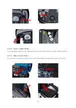


3.2.9
Hourmeter (Base)
The machine is equipped with an electronic hourmeter installed on the dashboard, which has a triple function:
Hourmeter
, for counting the totality of the machine’s working hours (only when it is in traction).
Display
, that allows to verify the setting of the Main Card and the possible alarm messages.
battery control board
, to keep under control the level of residual charge and stop the machine’s working
cycle in case the discharge threshold of the battery is close to levels that could compromise the life cycle. The
device can be adjusted according to the type of batteries installed on the machine.
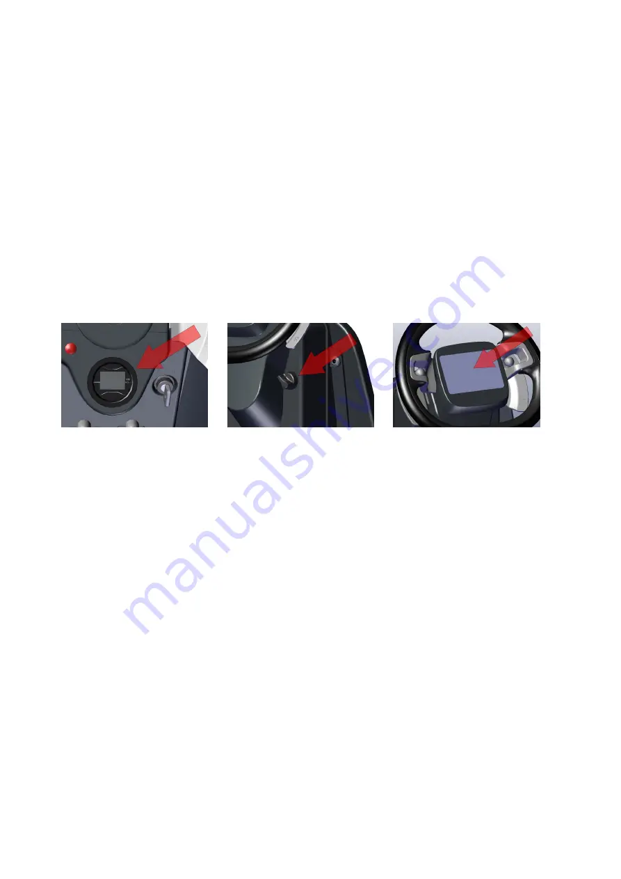
3.2.10
Display Touchscreen (Plus)
The machine is equipped with a touchscreen display which allows to control the devices of the machine and to
change the operating parameters.
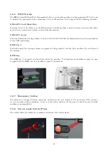
3.2.11
Key switch
The key switch provides the power supply to the whole machine.
3.2.12
Extra pressure Lever
The lever allows the switch to increase the pressure exerted on the central brushes.
With extra pressure
activated, a warning light is displayed on the steering column (Base), or on the display (Full).
3.2.13
Extra pressure warning light (Base)
The warning light lights up when the extra pressure is on.
3.2.14
Backward Lever
The lever allows the switch to activate the reverse traction and the acoustic signal.
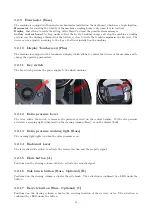
3.2.15
Horn button (A)
Positioned on the steering column, allows to activate the acoustic signal.
3.2.16
Side brush button (Base, Optional) (B)
Positioned on the steering column, activates the side brush. The activation is confirmed by a LED under the
button.
3.2.17
Recycle button (Base, Optional) (C)
Positioned on the steering column, activates the recycling function of the recovery water. The activation is
confirmed by a LED under the button.
35
Summary of Contents for 108538
Page 1: ...SERVICE MANUAL TRIDENT R30SC R28SC Version AA Date August 5 2019 Document Number 100x...
Page 4: ...Part I Product Introduction 4...
Page 10: ...1 6 Machine Dimensions 1 6 1 R30SC 10...
Page 11: ...1 6 2 R28SC 11...
Page 15: ...Part II Anomalies Resolution Guide 15...
Page 24: ...Part III Functional Groups 24...
Page 26: ...3 2 Location of Electrical Components 3 2 1 R30SC R28SC Plus 26...
Page 28: ...3 2 3 R30SC Base 28...
Page 64: ...4 6 Related electrical circuit 4 6 1 R30SC Base 64...
Page 66: ...4 6 2 R30SC PLUS 66...
Page 76: ...5 6 Related electrical circuit 5 6 1 R28SC PLUS 76...
Page 84: ...6 6 Related electrical circuit 6 6 1 R28SC Base 84...
Page 86: ...6 6 2 R30SC R28SC PLUS 86...
Page 94: ...7 5 Related electrical circuit 7 5 1 R30SC Base 94...
Page 96: ...7 5 2 R30SC R28SC PLUS 96...
Page 104: ...8 5 Related electrical circuit 8 5 1 R30SC Base 104...
Page 106: ...8 5 2 R30SC R28SC PLUS 106...
Page 112: ...Part IV Accessories and Add On 112...


