


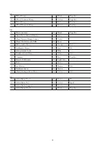


3.3.2
Function Alarms
Id Alarm
Meaning
Solution
AL 41
Function
Overtemperature
The temperature of the functions power mosfets exceeds 90
°
C.
Switch off the machine, wait for the cooling and then switch on
again.
AL 42
Function
Powerstage failure
Verify the machine model setting, turn it off and on again. If the
problem persists, replace the main card.
AL 43
Function
Main fuse failure
Check the Function fuse. If the problem persists, replace the main
card.
AL 44
Function
Main relay failure
Replace the main card.
AL 45
Function
Main relay failure
CC
Replace the main card.
AL 46
Function
Overcurrent brush
motor 1-2-3
Brushes Short Circuit.
Check the connections, if the problem
persists, replace the main card.
AL 47
Function
Overcurrent
vac-
uum motor 1-2
Vacuum Short Circuit. Check the connections, if the problem
persists, replace the main card.
AL 48
Function
Overcurrent pump
Pumps Short Circuit. Check the connections, if the problem per-
sists, replace the main card.
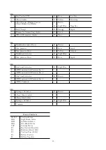
AL 49
Function
Brushes motor 1
Ammeter
Overcurrent of the Motor (Orbital), or Leftside Brush Motor
(Disc)
AL 50
Function
Brushes motor 2
Ammeter
Overcurrent of the Rightside Brush Motor (Disc)
AL 51
Function
Brushes motor 3
Ammeter
Overcurrent of the Right Brush Motor / Motors
AL 52
Function
Vacuum motor 1
Ammeter
Overcurrent of the Vacuum Motor.
AL 61
Function
Actuator1: Amme-
ter
Overcurrent of the Central brushdeck Actuator.
AL 62
Function
Actuator1:
Overcurrent
Brushes Actuator Short Circuit. Check the connections, if the
problem persists, replace the main card.
AL 65
Function
Actuator2: Amme-
ter
Overcurrent of the Side brushdeck/s Actuator/s.
AL 66
Function
Actuator2:
Overcurrent
Side Brushes Actuator Short Circuit. Check the connections, if
the problem persists, replace the main card.
AL 69
Function
Actuator3: Amme-
ter
Overcurrent of the Squeegee Actuator.
AL 70
Function
Actuator3:
Overcurrent
Squeegee Actuator Short Circuit. Check the connections, if the
problem persists, replace the main card.
42
Summary of Contents for 108538
Page 1: ...SERVICE MANUAL TRIDENT R30SC R28SC Version AA Date August 5 2019 Document Number 100x...
Page 4: ...Part I Product Introduction 4...
Page 10: ...1 6 Machine Dimensions 1 6 1 R30SC 10...
Page 11: ...1 6 2 R28SC 11...
Page 15: ...Part II Anomalies Resolution Guide 15...
Page 24: ...Part III Functional Groups 24...
Page 26: ...3 2 Location of Electrical Components 3 2 1 R30SC R28SC Plus 26...
Page 28: ...3 2 3 R30SC Base 28...
Page 64: ...4 6 Related electrical circuit 4 6 1 R30SC Base 64...
Page 66: ...4 6 2 R30SC PLUS 66...
Page 76: ...5 6 Related electrical circuit 5 6 1 R28SC PLUS 76...
Page 84: ...6 6 Related electrical circuit 6 6 1 R28SC Base 84...
Page 86: ...6 6 2 R30SC R28SC PLUS 86...
Page 94: ...7 5 Related electrical circuit 7 5 1 R30SC Base 94...
Page 96: ...7 5 2 R30SC R28SC PLUS 96...
Page 104: ...8 5 Related electrical circuit 8 5 1 R30SC Base 104...
Page 106: ...8 5 2 R30SC R28SC PLUS 106...
Page 112: ...Part IV Accessories and Add On 112...


