7.2
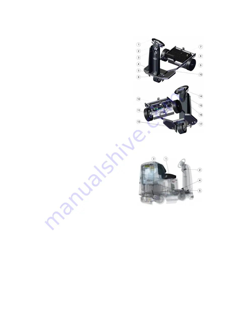
Main Components
1
Steering Wheel
2
Backward switch
3
Max Pressure Switch
4
Accelerator Pedal
5
Brake Pedal
6
Brake Pedal microswitch
7
Battery Tray
8
Traction Gearmotor
9
Electrobrake
10
Frame
11
Rear Splashguard
12
Rear Wheels
13
Front Wheels
14
Touchscreen Display
15
Key Switch
16
Horn
17
Steering Chain
7.3
Work requirements
The traction unit only works if the following conditions are met:
The batteries are not discharged.
The operator is seated on the machine so as to press the
seat safety switch (1).
The machine is on (2).
The electrobrake is activated (3).
The brake pedal is not pressed (4).
The accelerator pedal is pressed (5).
92
Summary of Contents for 108538
Page 1: ...SERVICE MANUAL TRIDENT R30SC R28SC Version AA Date August 5 2019 Document Number 100x...
Page 4: ...Part I Product Introduction 4...
Page 10: ...1 6 Machine Dimensions 1 6 1 R30SC 10...
Page 11: ...1 6 2 R28SC 11...
Page 15: ...Part II Anomalies Resolution Guide 15...
Page 24: ...Part III Functional Groups 24...
Page 26: ...3 2 Location of Electrical Components 3 2 1 R30SC R28SC Plus 26...
Page 28: ...3 2 3 R30SC Base 28...
Page 64: ...4 6 Related electrical circuit 4 6 1 R30SC Base 64...
Page 66: ...4 6 2 R30SC PLUS 66...
Page 76: ...5 6 Related electrical circuit 5 6 1 R28SC PLUS 76...
Page 84: ...6 6 Related electrical circuit 6 6 1 R28SC Base 84...
Page 86: ...6 6 2 R30SC R28SC PLUS 86...
Page 94: ...7 5 Related electrical circuit 7 5 1 R30SC Base 94...
Page 96: ...7 5 2 R30SC R28SC PLUS 96...
Page 104: ...8 5 Related electrical circuit 8 5 1 R30SC Base 104...
Page 106: ...8 5 2 R30SC R28SC PLUS 106...
Page 112: ...Part IV Accessories and Add On 112...


