


7.7
Disassembly
7.7.1
Touchscreen Display
Unscrew the 6 screws of the nose and remove it.
Unscrew the headless screw.
Slide out the display and remove the 4 screws on the back.
Open the display and remove connectors 1-2.
7.7.2
Front Wheel
Lift up the front wheels from the ground. Remove the screw
that secures the two wheels to the shaft. Remove the shaft being
careful to keep the spacers inserted between the two wheels.
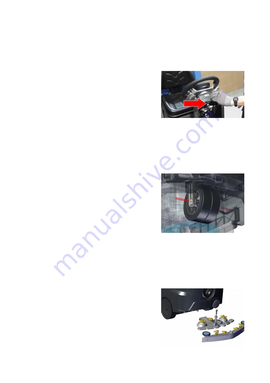
7.7.3
Traction Gearmotor
Lift the machine with a suitable hydraulic system or similar de-
vice. Remove the squeegee
(see section
at page
. Remove both
rear wheels of the machine.
99
Summary of Contents for 108538
Page 1: ...SERVICE MANUAL TRIDENT R30SC R28SC Version AA Date August 5 2019 Document Number 100x...
Page 4: ...Part I Product Introduction 4...
Page 10: ...1 6 Machine Dimensions 1 6 1 R30SC 10...
Page 11: ...1 6 2 R28SC 11...
Page 15: ...Part II Anomalies Resolution Guide 15...
Page 24: ...Part III Functional Groups 24...
Page 26: ...3 2 Location of Electrical Components 3 2 1 R30SC R28SC Plus 26...
Page 28: ...3 2 3 R30SC Base 28...
Page 64: ...4 6 Related electrical circuit 4 6 1 R30SC Base 64...
Page 66: ...4 6 2 R30SC PLUS 66...
Page 76: ...5 6 Related electrical circuit 5 6 1 R28SC PLUS 76...
Page 84: ...6 6 Related electrical circuit 6 6 1 R28SC Base 84...
Page 86: ...6 6 2 R30SC R28SC PLUS 86...
Page 94: ...7 5 Related electrical circuit 7 5 1 R30SC Base 94...
Page 96: ...7 5 2 R30SC R28SC PLUS 96...
Page 104: ...8 5 Related electrical circuit 8 5 1 R30SC Base 104...
Page 106: ...8 5 2 R30SC R28SC PLUS 106...
Page 112: ...Part IV Accessories and Add On 112...


