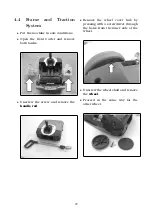

5.3.5
Batteries
and
battery
Charger
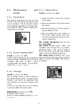
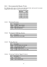
The
battery
on this machine is equipped
with a built-in control Card with LED
indicator.
When the remaining power
decreases, the LEDs gradually go off in
sequence, when the charge comes to
10% the card in the battery cuts the
power
(see fig.
.
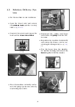
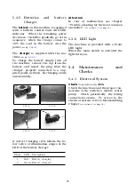
The
charger
is supplied with the ma-
chine
(see fig.
.
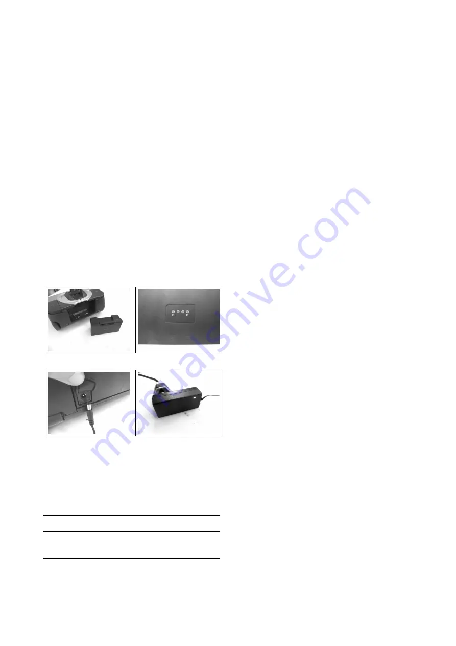
To charge the battery simply turn off
the machine, remove the cap from the
battery and insert the plug from the
charger, properly connected to a sup-
plied power network. Recharging starts
automatically.
5.3.5-4
5.3.5-5
5.3.5-6
5.3.5-7
A correct Charging cycle follows the be-
low series of illumination stages of the
LED of the battery charger.
Phase
LED Description
1
Red
Battery charging
2
Green Battery charged
Attention
In case of malfunction see chapter
”‘Trouble-shooting for the most common
anomalies”’
(see section
at page
.
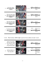
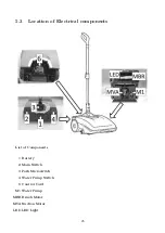
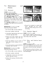
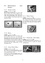
5.3.6
LED Light
The machine is provided with a Front
LED Light.
When the main switch is activated the
light turns on.
5.4
Maintenance
and
Checks
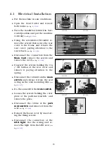
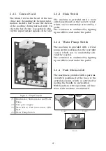
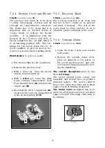
5.4.1
Electrical System
Check
(to perform every
150h
)
Check the functions and the proper con-
nections of the switches, motors, water
pump.
Check periodically, the wiring
connections status.
To access to the
electrical system, refer to Disassembling
Chapter
(see section
at page
.
28


