
7.3
Maintenance
and
Checks
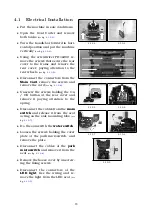
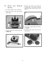
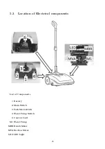
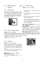
7.3.1
Squeegee
Check
(to perform every
2h
)
To have a good performance
The
squeegee chamber
have to be clean
and completely free from debris.
The
squeegee blades
have to be in a
good conditions; they have to adhere
perfectly to the squeegee body and have
to be kept in that position by the plastic
wing nuts.
The
squeegee wheels
must be in good
condition and rotate free from any ob-
struction.
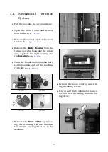
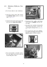
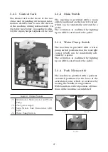
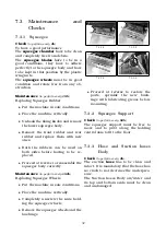
Maintenance
(to perform every
15h
)
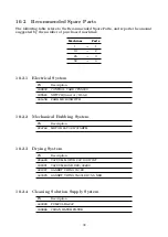
Replacing Squeegee Rubber
•
Put the machine in safe conditions.
•
Place the machine vertically.
•
Unhook the fixing knobs and remove
the lower squeegee body.
•
Remove the front rubber and rear
rubber and replace them with new
ones.
•
Both the rubbers can be used on
both sides before having to be re-
placed.
•
Proceed at reverse to reassemble the
squeegee body correctly.
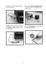
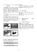
Maintenance
(to perform every
150h
)
Replacing Squeegee Wheels
•
Put the machine in safe conditions.
•
Place the machine vertically.
•
Completely unscrew the nuts hold-
ing the squeegee wheels
•
Remove the squeegee wheels and the
bushings
7.3.1-1
7.3.1-2
7.3.1-3
7.3.1-4
•
Proceed at reverse to restore the
parts,
sprinkle
the
new
bush-
ings with lubricating grease before
mounting.
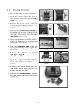
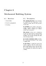
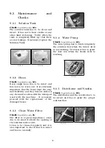
7.3.2
Squeegee Support
Check
(to perform every
50h
)
The squeegee support must be free to
move and to pivot along the holding
central axis to fit to the floor.
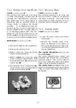
7.3.3
Hose and Suction hoses
Body
Check
(to perform every
2h
)
The suction
hose
has to be clean and
intact. It is mandatory that the hose has
no crack to not decrease the underpres-
sure.
The Suction hoses Body air/water and
its top and bottom seals must be clean
and undamaged.
32


