background image

ESP

AÑOLA

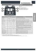
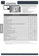
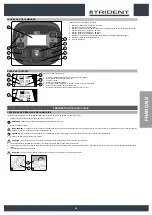
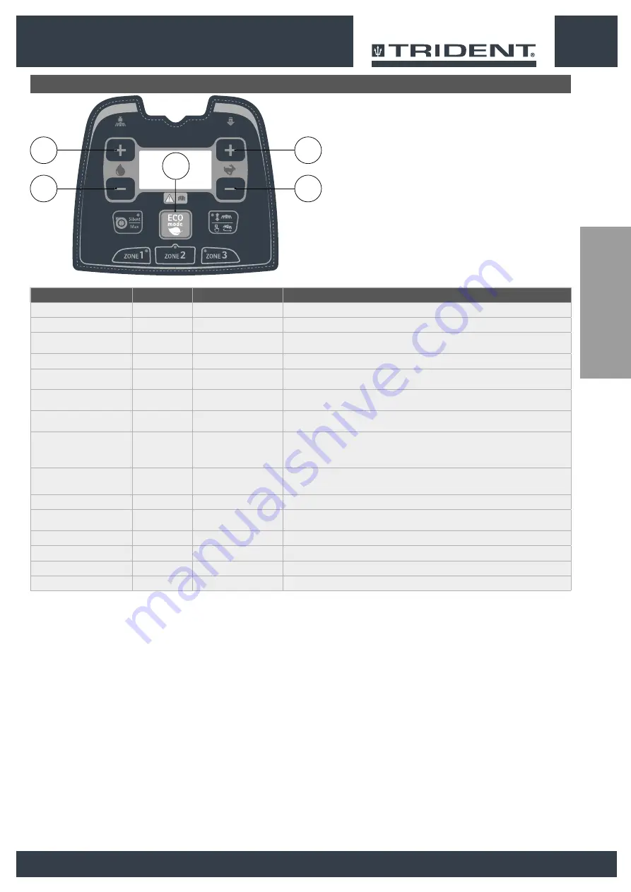
NAVEGACIÓN MENÚ PANTALLA DE MANDOS

Para acceder a la pantalla del menú, encender la máquina mientras se presionan y se 

mantienen presionados los pulsadores (2) y (3). Después de la primera vista, se visualizará 

el MENÚ GENERAL.

Para navegar por los menús, utilizar las teclas:

Pulsador (1) de deslizamiento al parámetro siguiente.

Pulsador (2) de deslizamiento al parámetro anterior.

Pulsador (3) para aumentar en una unidad el valor seleccionado.

Pulsador (4) para disminuir en una unidad el valor seleccionado.

Pulsador (5) confirmar el valor y salir del menú operador.

3s.

1

3

5

2

4

MENÚ

DEFAULT

VALORES CONFIGURABLES

DESCRIPCIÓN

Language selection:

IT

IT / EN / FR / SP / DE

Esta función permite seleccionar el idioma de la pantalla.

Model selection:

Name Model

Esta función permite seleccionar el modelo de la máquina.

Battery selection:

Gel60

Pb60 / Gel60 / PPb / Pb80 

/ Gel80

Esta función permite seleccionar el tipo de batería que se desea utilizar en la máquina.

Reset Count-Meter

No reset

No Reset / Reset

Esta función permite poner a cero el contador de horas que se visualiza en la pantalla.

Display Count-Meter

Traction

Traction / Key-On

Esta función permite seleccionar el tipo de contador de horas que se quiere visualizar en la pantalla. 

KEY-

ON

: conectado a la llave de encendido. 

TRACTION

: conectado al motor de tracción.

Display Tune

15

5÷50

Esta función permite regular el contraste de la pantalla. El valor se extiende entre un mínimo de 5 hasta un 

máximo de 50, con incrementos de a una unidad.

Display Brightness

0

0÷10

Esta función permite regular el brillo de la pantalla. El valor se extiende entre un mínimo de 0 hasta un 

máximo de 10, con incrementos de a una unidad.

Solution Management

None

None / FLR / HDC

Esta función permite seleccionar la forma de administrar el producto detergente. 

None

: el detergente 

utilizado es administrado manualmente por el operador. 

HDC: 

el agua y el detergente son dosificados 

automáticamente por la máquina. 

FLR: 

función que permite la recirculación de la solución detergente en 

modo continuo.

Wand / Spray Selectiom

None

None / Wand / Spray

Esta función permite activar o desactivar los accesorios opcionales, como la lanza de aspiración de líquidos 

o la pistola rociadora. 

None

: no hay ningún accesorio opcional. 

Wand: 

la función del accesorio lanza de 

aspiración de líquidos está activa. 

Spray: 

la función del accesorio pistola de rociado está activa.

Exit

N

Y/N

Esta función permite salir del menú del operador.

Key-on Count-meter

-

-

Esta función permite visualizar el contador de horas total de uso de la máquina (referido a la llave de 

arranque).

Traction motor Count-meter

-

-

Esta función permite visualizar el contador de horas total del motor de tracción.

Brushes motor Count-meter

-

-

Esta función permite visualizar el contador de horas total del motor del cepillo.

Vacuum motor Count-meter

-

-

Esta función permite visualizar el contador de horas total del motor aspiración.

-ID CHECK- Password

-

-

Esta función permite ingresar la contraseña para acceder al “menú avanzado”.

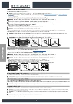
Para modificar el valor de un parámetro, proceder de la siguiente manera:

1. 

Desplazarse por los submenús con el pulsador (1) y (2) hasta identificar el parámetro que se desea modificar.

2. 

Utilizar los pulsadores (3) y (4) para desplazarse por la lista de valores disponibles para el parámetro que se desea modificar.

3. 

Para habilitar el cambio realizado se debe volver al menú de trabajo. Para salir del menú operador seleccionando el submenú de salida y confirmar con el pulsador (5).

55

Summary of Contents for TRIDENT R26SC PRO

Page 1: ...Original istruction DOC 10085917 Ver AA 02 2019 Scrubbing machine Fregadora de pavimento Autolaveuses Use and Maintenance manual Manual de uso y mantenimiento Manuel d utilisation et d entretien...

Page 2: ......

Page 3: ...ENGLISH 4 ESPA OLA 30 FRAN AIS 56 3 ESPA OLA FRAN AIS ENGLISH...

Page 4: ...INE 11 HOW TO UNPACK THE MACHINE 11 HOW TO MOVE THE MACHINE 12 MACHINE SAFETY 12 INSERTING THE BATTERIES IN THE MACHINE 12 BATTERY MAINTENANCE AND DISPOSAL 12 RECHARGING THE BATTERIES 12 FILLING THE S...

Page 5: ...BRUSH HEAD BRUSHES SCRUBBING 22 CLEANING THE RECOVERY TANK FILTERS 23 EMPTYING THE SOLUTION TANK 24 CLEANING THE VACUUM TUBE 24 CLEANING THE WATER SYSTEM FILTER 24 CLEANING THE DETERGENT TANK HDC VER...

Page 6: ...21 Automatic detergent dosing optional kit control button HDC version 22 Optional spray gun kit control button 23 Optional liquid suction wand kit control button 24 Steering wheel 25 Reverse gear sel...

Page 7: ...ors must not perform operations that should be carried out by qualified technicians The manufacturer is not liable for damages resulting from failure to comply with this veto PRESERVATION OF THE USER...

Page 8: ...cal weight of 75kg 8 TECHNICAL DATA U M U S C U TRIDENT R26SC Pro Rated machine power W 1722 Working capacity up to sq ft h 24488 Working width in 25 5 Squeegee width in 30 79 Central brush head brush...

Page 9: ...on tank to indicate the amount of water or detergent solution in the tank The symbol on the side indicates that the tank is full to about three quarters of its capacity Solution tank filling symbol Lo...

Page 10: ...e HDC system without damaging it Detergent dilution label versions with HDC Used in the vicinity of the detergent tank to indicate the capacity of the detergent tank and the dilution percentage of the...

Page 11: ...of children disabled persons etc CAUTION these operations must be carried out using protective gloves to avoid any possible contact with the edges or tips of metal objects 3 Insert a ramp in the rear...

Page 12: ...ontact the nearest HILLYARD assistance centre to modify the setting if you want to use gel batteries CAUTION to avoid any permanent damage to the batteries it is essential to avoid their complete disc...

Page 13: ...ctor may cause problems with machine functioning NB Carefully read the use and maintenance instructions of the battery charger that is used for charging this document is delivered along with the machi...

Page 14: ...achine see the section titled SECURING THE MACHINE 3 Press the recovery tank release lever 1 and turn the recovery tank into the maintenance position Fig 1 4 Disconnect the male insert 2 from the fema...

Page 15: ...amount of detergent solution present in the solution tank is sufficient for the type of work to be performed If this is not the case top up the solution tank see the sections titled FILLING THE SOLUT...

Page 16: ...will switch on Fig 2 5 Lower the squeegee body and press the SQUEEGEE CONTROL button 4 on the control panel Fig 2 N B as soon as the button 4 on the control panel is pressed the green LED 5 SQUEEGEE B...

Page 17: ...efficiency are pre set and have been created on the basis of the type of environment where you want to work To select an area program just press the relative button 1 on the control panel Fig 1 N B w...

Page 18: ...ensed by the machine is proportional in a percentage defined by a pre set parameter in the machine to the water flow rate present in the water circuit of the machine 1 1 EMERGENCY BUTTON If any seriou...

Page 19: ...OPTIONAL Upon request the machine can be fitted with the VACUUM WAND system that vacuums up the detergent solution more accurately To start it do as follows 1 Lift the brush head body and press the BR...

Page 20: ...7 Sit on the driver s seat 8 Insert the key 6 into the main switch on the control panel Set the main switch to I Fig 4 9 Press the drive pedal 5 Fig 2 to begin moving the machine 10 Take the appliance...

Page 21: ...RK POSITION will switch off Fig 1 CAUTION these operations must be carried out using protective gloves to avoid any possible contact with the edges or tips of metal objects 4 Extract the vacuum hose 5...

Page 22: ...on the control panel is pressed the green LED 2 BRUSH HEAD BODY WORK POSITION will switch off Fig 1 3 Lift the squeegee body and press the SQUEEGEE CONTROL button 3 on the control panel Fig 1 N B as s...

Page 23: ...he control panel Fig 1 N B as soon as the button 3 on the control panel is pressed the green LED 4 SQUEEGEE BODY WORK POSITION will switch off Fig 1 4 Stand at the back of the machine CAUTION users ar...

Page 24: ...UM TUBE Careful cleaning of the vacuum hose guarantees better cleaning of the floor as well as a longer suction motor life Proceed as follows to clean the vacuum hose 1 Take the machine to the mainten...

Page 25: ...Remove the cap 5 from the detergent canister Fig 4 7 Rinse the inside of the canister with a jet of running water N B the place designated for this operation must comply with current environmental pr...

Page 26: ...tch to I Fig 1 3 Lower the brush head body and press the BRUSH HEAD CONTROL button 2 on the control panel Fig 2 N B as soon as the button 2 on the control panel is pressed the green LED 3 BRUSH HEAD B...

Page 27: ...e section titled SECURING THE MACHINE ATTENTION these operations must be carried out using protective gloves to avoid any possible contact with the edges or tips of metal objects 7 Go to the front lef...

Page 28: ...quired by the battery charger Check that the characteristics in the battery charger plate are the same as those of the mains supply The LEDs of the battery charger blink repeatedly Referring to the ba...

Page 29: ...f 10 with unitary increments Solution Management None None FLR HDC This function enables the operator to select how to manage the detergent product None The detergent used is managed manually by the o...

Page 30: ...C MO TRANSPORTAR LA M QUINA 38 CONDICIONES DE SEGURIDAD DE LA M QUINA 38 INTRODUCCI N DE LAS BATER AS EN LA M QUINA 38 MANTENIMIENTO Y ELIMINACI N DE LAS BATER AS 38 RECARGA DE LAS BATER AS 38 LLENAD...

Page 31: ...MPIEZA FILTROS DEL TANQUE DE RECUPERACI N 49 VACIADO DEL TANQUE SOLUCI N 50 LIMPIEZA DEL TUBO ASPIRACI N 50 LIMPIEZA DEL FILTRO DE LA INSTALACI N H DRICA 50 LIMPIEZA DEL TANQUE DE DETERGENTE VERSIONES...

Page 32: ...esi n bancada 20 Pulsador del avisador ac stico 21 Pulsador de mando del kit opcional del dosificador autom tico de detergente versi n HDC 22 Pulsador de mando kit opcional pistola de limpieza de los...

Page 33: ...os t cnicos cualificados para el mantenimiento de la m quina Los operadores no deben realizar las operaciones reservadas a los t cnicos cualificados La empresa productora no responder por da os deriva...

Page 34: ...a nominal de la m quina W 1722 Capacidad de trabajo hasta ft2 h 24488 Anchura de trabajo in 25 5 Anchura boquilla de aspiraci n in 30 79 Cepillos bancada central n mero Di m cerdas externas N in 2 13...

Page 35: ...zquierda del tanque soluci n de la m quina para indicar la cantidad de agua o de soluci n detergente que contiene El s mbolo de al lado indica que el tanque tiene tres cuartos de su capacidad S mbolo...

Page 36: ...H se puede utilizar con el sistema HDC sin da arlo Etiqueta diluci n detergente versiones con HDC Se utiliza cerca del tanque de detergente para indicar la capacidad del tanque de detergente y el porc...

Page 37: ...rmanecer al alcance de los ni os de personas minusv lidas etc PRUDENCIA Estas operaciones deben realizarse utilizando guantes para protegerse del posible contacto con bordes o puntas de objetos met li...

Page 38: ...tro de asistencia HILLYARD m s cercano para cambiar la configuraci n si desea utilizar bater as de gel PRUDENCIA Para no provocar da os permanentes a las bater as es indispensable evitar que las misma...

Page 39: ...r el malfuncionamiento de la m quina NOTA Leer atentamente el manual de uso y mantenimiento del cargador de bater as que se utiliza para realizar la recarga este documento se entrega junto con la m qu...

Page 40: ...eguridad leer el apartado CONDICIONES DE SEGURIDAD DE LA M QUINA 3 Presionar la palanca de desenganche del tanque de recuperaci n 1 y girar a la posici n de mantenimiento el tanque de recuperaci n Fig...

Page 41: ...tanque soluci n sea adecuada para el tipo de trabajo que se desea realizar en caso contrario proceder al llenado del tanque soluci n leer los apartados LLENADO DEL TANQUE SOLUCI N y SOLUCI N DETERGENT...

Page 42: ...Bajar el cuerpo de la boquilla de aspiraci n y presionar el pulsador MANDO DE LA BOQUILLA DE ASPIRACI N 4 situado en el panel de mandos Fig 2 NOTA Apenas se presiona el pulsador 4 en el panel de mand...

Page 43: ...Rendimiento del motor aspiraci n Est n predeterminadas espec ficamente para el tipo de ambiente en el cual se desea trabajar Para seleccionar un program zone basta con presionar el pulsador correspond...

Page 44: ...porcional en un porcentaje definido por un par metro preestablecido en la m quina al caudal de agua existente en el circuito h drico de la m quina 1 1 PULSADOR DE EMERGENCIA Si durante el trabajo surg...

Page 45: ...OPCIONAL Opcionalmente se puede instalar en la m quina el sistema LANZA DE ASPIRACI N que permite aspirar con mayor precisi n la soluci n detergente anteriormente vertida Para activarlo efectuar las...

Page 46: ...cci n 8 Colocar la llave 6 en el interruptor general del panel de mando Colocar el interruptor general en la posici n I Fig 4 9 Pisar el pedal de marcha 5 Fig 2 para que la m quina comience a moverse...

Page 47: ...CUERPO BOQUILLA DE ASPIRACI N EN POSICI N DE TRABAJO Fig 1 PRUDENCIA Estas operaciones deben realizarse utilizando guantes para protegerse del posible contacto con bordes o puntas de objetos met lico...

Page 48: ...o de la boquilla de aspiraci n y presionar el pulsador MANDO DE LA BOQUILLA DE ASPIRACI N 3 situado en el panel de mandos Fig 1 NOTA Apenas se presiona el pulsador 3 en el panel de mandos se apagar el...

Page 49: ...s se presiona el pulsador 3 en el panel de mandos se apagar el led verde 4 CUERPO BOQUILLA DE ASPIRACI N EN POSICI N DE TRABAJO Fig 1 4 Posicionarse en la parte trasera de la m quina PRUDENCIA Se reco...

Page 50: ...idadosa del tubo de aspiraci n garantiza una mejor limpieza del pavimento y una mayor duraci n del motor aspiraci n Para limpiar el tubo aspiraci n realizar lo siguiente 1 Colocar la m quina en el lug...

Page 51: ...n de detergente Fig 4 7 Enjuagar el interior del bid n con un chorro de agua corriente NOTA El lugar previsto para esta operaci n debe estar en conformidad con la normativa vigente de respeto al medi...

Page 52: ...ando Colocar el interruptor general en posici n I Fig 1 3 Bajar el cuerpo de la bancada presionar el pulsador MANDO BANCADA 2 presente en el panel de mandos Fig 2 NOTA Apenas se presiona el pulsador 2...

Page 53: ...ner la m quina en condiciones de seguridad leer el apartado CONDICIONES DE SEGURIDAD DE LA M QUINA ATENCI N Estas operaciones deben realizarse utilizando guantes para protegerse del posible contacto c...

Page 54: ...la placa del cargador sean iguales a las de la red de alimentaci n Los leds del cargador de bater as parpadean repetidamente Controlar consultando el manual de uso y mantenimiento del cargador de bat...

Page 55: ...0 con incrementos de a una unidad Solution Management None None FLR HDC Esta funci n permite seleccionar la forma de administrar el producto detergente None el detergente utilizado es administrado man...

Page 56: ...ALLAGE DE LA MACHINE 63 COMMENT TRANSPORTER LA MACHINE 64 MISE EN S CURIT DE LA MACHINE 64 INSERTION DES BATTERIES DANS LA MACHINE 64 ENTRETIEN ET MISE AU REBUT DES BATTERIES 64 RECHARGE DES BATTERIES...

Page 57: ...74 NETTOYAGE DES FILTRES DU R SERVOIR DE R CUP RATION 75 VIDANGE DU R SERVOIR DE SOLUTION 76 NETTOYAGE DU FLEXIBLE D ASPIRATION 76 NETTOYAGE FILTRE SYST ME HYDRIQUE 76 NETTOYAGE DE LA CUVE DU D TERGEN...

Page 58: ...pl mentaire du carter 20 Bouton de l avertisseur sonore 21 Bouton de commande du kit en option doseur automatique du d tergent version HDC 22 Bouton de commande du kit en option pistolet de nettoyage...

Page 59: ...qualifi s pour l entretien de la machine Les op rateurs ne doivent pas effectuer d op rations r serv es aux techniciens qualifi s Le fabricant n est pas responsable pour des dommages d rivant du non r...

Page 60: ...S U d M U S C U TRIDENT R26SC Pro Puissance nominale de la machine W 1722 Capacit de travail jusqu ft2 h 24488 Largeur de travail in 25 5 Largeur du suceur in 30 79 Brosses du carter central nombre br...

Page 61: ...voir de solution Il est utilis dans le c t gauche du r servoir de solution de la machine pour indiquer la quantit d eau ou de solution d tergente pr sente son int rieur Le symbole ci contre indique qu...

Page 62: ...utilis avec le syst me HDC sans l endommager tiquette de dilution du d tergent versions avec HDC Elle est utilis e proximit de la cuve du d tergent pour indiquer la capacit de la cuve du d tergent et...

Page 63: ...des personnes handicap es etc PRUDENCE ces op rations doivent tre effectu es en utilisant des gants pour se prot ger contre tout contact avec des bords ou pointes d objets m talliques 3 Positionner un...

Page 64: ...LLYARD le plus proche pour modifier la configuration afin d utiliser des batteries au gel PRUDENCE pour ne pas endommager irr parablement les batteries il faut viter que celles ci ne se d chargent com...

Page 65: ...re attentivement le manuel d utilisation et d entretien du chargeur de batterie utilis pour effectuer la recharge Ce document est remis avec la machine I Tourner le r servoir de r cup ration jusqu ce...

Page 66: ...ne lire le paragraphe MISE EN S CURIT DE LA MACHINE 3 Appuyer sur le levier de d crochage du r servoir de r cup ration 1 et tourner en position d entretien le r servoir de r cup ration Fig 1 4 D branc...

Page 67: ...e r servoir de solution lire les paragraphes REMPLISSAGE DU R SERVOIR DE SOLUTION et SOLUTION D TERGENTE 3 V rifier si l tat des bavettes du suceur est apte au travail effectuer Dans le cas contraire...

Page 68: ...DE TRAVAIL s allume Fig 2 5 Abaisser le corps du suceur appuyer sur le bouton COMMANDE DU SUCEUR 4 pr sent sur le panneau de commande Fig 2 REMARQUE D s l appui sur le bouton 4 du panneau de commande...

Page 69: ...l s et con us en fonction du type d environnement dans lequel on envisage de travailler Pour s lectionner un program zone il suffit d appuyer sur le bouton correspondant 1 pr sent sur le panneau de co...

Page 70: ...distribu e par la machine est proportionnelle selon un pourcentage d fini par un param tre pr d fini dans la machine au d bit d eau pr sent dans le circuit d eau de la machine 1 1 BOUTON D ARR T D UR...

Page 71: ...mande Fig 1 1 1 2 KIT LANCE D ASPIRATION EN OPTION Sur demande la machine peut tre dot e du syst me LANCE D ASPIRATION un syst me permettant d aspirer de mani re plus pr cise la solution d tergente ve...

Page 72: ...ste de conduite 8 Introduire la cl 6 dans l interrupteur g n ral pr sent sur le panneau de commande Mettre l interrupteur g n ral sur I Fig 4 9 Quand on appuie sur la p dale de marche 5 Fig 2 la machi...

Page 73: ...en utilisant des gants pour se prot ger contre tout contact avec des bords ou pointes d objets m talliques 4 Extraire le tuyau d aspiration 5 de la bouche d aspiration dans le corps du suceur Fig 2 5...

Page 74: ...suceur appuyer sur le bouton COMMANDE DU SUCEUR 3 pr sent sur le panneau de commande Fig 1 REMARQUE D s l appui sur le bouton 3 du panneau de commande la DEL verte 4 CORPS SUCEUR POSITION DE TRAVAIL s...

Page 75: ...au de commande la DEL verte 4 CORPS SUCEUR POSITION DE TRAVAIL s teint Fig 1 4 Se placer l arri re de la machine PRUDENCE il est conseill de toujours porter des gants de protection pour viter des bles...

Page 76: ...GE DU FLEXIBLE D ASPIRATION Le nettoyage minutieux du tuyau d aspiration garantit un meilleur nettoyage du sol ainsi qu une plus longue dur e du moteur d aspiration Pour nettoyer le tuyau d aspiration...

Page 77: ...e 5 D poser le r servoir de d tergent 4 du compartiment dans le r servoir de solution en appuyant sur la poign e du r servoir Fig 3 6 Enlever le bouchon 5 du r servoir de d tergent Fig 4 7 Rincer l in...

Page 78: ...ral pr sent sur le panneau de commande Mettre l interrupteur g n ral sur I Fig 1 3 Abaisser le corps du carter appuyer sur le bouton COMMANDE DU CARTER 2 pr sent sur le panneau de commande Fig 2 REMA...

Page 79: ...EN S CURIT DE LA MACHINE ATTENTION ces op rations doivent tre effectu es en utilisant des gants pour se prot ger contre tout contact avec des bords ou pointes d objets m talliques 7 Se placer l avant...

Page 80: ...erie Contr ler si les caract ristiques d crites dans la plaque du chargeur de batterie correspondent celles du r seau d alimentation Les voyants du chargeur clignotent de mani re r p t e V rifier sur...

Page 81: ...cr ment d une unit Solution Management None None FLR HDC Cette fonction permet de s lectionner comment g rer le produit d tergent None le d tergent utilis est g r de fa on manuelle par l op rateur HDC...

Page 82: ...ESPA OLA FRAN AIS ENGLISH 82...

Page 83: ......

Page 84: ...HILLYARD INDUSTRIES PO Box 909 St Joseph Missouri 64502 0909 U S A Telephone 816 233 1321 www hillyard com...

Reviews: