N.B.
: Figure 6 indicates the direction of rotation for tilting the squeegee towards the rear of the machine (
Fig.7
). Turn it in the opposite direction to rotate the squeegee towards the front of the machine.
N.B.
: Check for proper adjustment by looking at the instrument (10) positioned on the squeegee body (
Fig.8
).
7
8
6
9
10
ADJUSTING BRUSH HEAD BODY SIDE SPLASH GUARDS
If the side splash guards of the brush head body are not positioned correctly they cannot do their work properly, namely convey the dirty detergent solution towards the squeegee, therefore the height of the splash
guard needs to be adjusted.
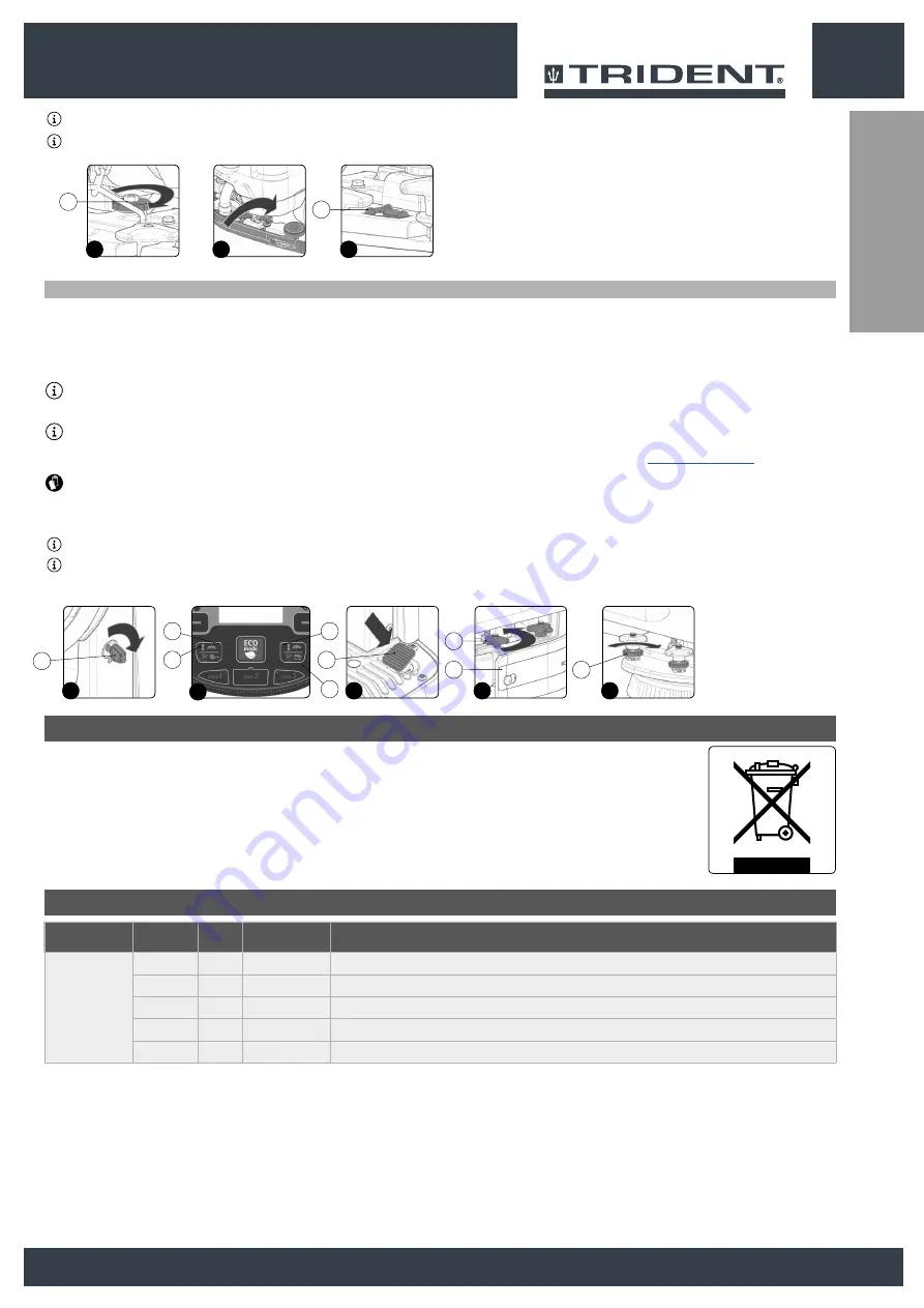
This operation can be done with the brush head body in the work position, proceeding as follows:
1. Sit on the driver’s seat.
2. Insert the key (1) into the main switch on the control panel. Set the main switch to "I" (
Fig.1
).
3. Lower the brush head body and press the “BRUSH HEAD CONTROL” button (2) on the control panel (
Fig.2
).
N.B.
:
as soon as the button (2) on the control panel is pressed, the green LED (3) (“BRUSH HEAD BODY WORK POSITION”) will switch on (
Fig.2
).
4. Lower the squeegee body and press the “SQUEEGEE CONTROL” button (4) on the control panel (
Fig.2
).
N.B.
:
as soon as the button (4) on the control panel is pressed, the green LED (5) (“SQUEEGEE BODY WORK POSITION”) will switch on (
Fig.2
).
5. Press the drive pedal (6) (
Fig.3
) to begin moving the machine.
ATTENTION:
these operations must be carried out using protective gloves to avoid any possible contact with the edges or tips of metal objects.
7.
Go to the front left-hand side of the machine.
8. Remove the left splash guard (7), unscrew the knobs (8) on the brush head body (
Fig.4
).
9.
Adjust the height of the splash guard with respect to the floor, tighten or loosen the knobs (9) until the splash guard touches the floor along its entire length (
Fig.5
).
N.B.
: By turning the knobs (9) clockwise, the splash guard support moves towards the floor (
Fig.5
).
N.B.
: Both the front and rear of the splashguard need to be at the same height off the floor.
10. Once the adjustment has been made, reposition the left splash guard (7) and tighten the knobs (8).
11. Repeat the operations just carried out also for the right side centre as well.
4
5
8
7
9
3
1
1
6
2
5
3
4
2
MACHINE
CODE
QTY
TYPE OF BRISTLE
NOTES
TRIDENT R26SC
422189
2
PPL Ø0,3
BRUSH Ø340mm Ø13.4in (LIGHT BLUE)
422971
2
PPL Ø0,6
BRUSH Ø340mm Ø13.4in (WHITE)
422972
2
PPL Ø0,9
BRUSH Ø340mm Ø13.4in (BLACK)
422981
2
ABRASIVE
BRUSH Ø340mm Ø13.4in
422973
2
-
PAD HOLDER Ø320mm Ø12.6in
DISPOSAL
To dispose of the machine, take it to a demolition centre or an authorised collection centre.
Before scrapping the machine, it is necessary to remove and separate out the following materials, then send them to the appropriate collection centres in accordance with the
environmental hygiene regulations currently in force:
• Brushes
• Felt
• Electric and electronic parts*
• Batteries
• Plastic parts (tanks and handlebars)
• Metal parts (levers and frame)
(*) In particular, contact your distributor when scrapping electric and electronic parts.
BRUSH TYPE
27
Summary of Contents for TRIDENT R26SC PRO
Page 2: ......
Page 3: ...ENGLISH 4 ESPA OLA 30 FRAN AIS 56 3 ESPA OLA FRAN AIS ENGLISH...
Page 82: ...ESPA OLA FRAN AIS ENGLISH 82...
Page 83: ......


