


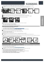
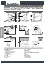
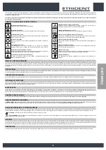
FUNCIÓN EXTRA-PRESIÓN BANCADA DE LOS CEPILLOS
Esta máquina tiene la posibilidad de añadir presión en el cepillo durante el trabajo, para ello proceder del siguiente modo:
1.
Verificar que el cuerpo de la bancada esté en contacto con el pavimento; en caso contrario, intervenir en el pulsador "MANDO BANCADA" (1) presente en el panel de mandos (
Fig. 1
).
NOTA
:
Apenas se presiona el pulsador (1), en el panel de mandos se encenderá el led verde (2) “CUERPO BANCADA EN POSICIÓN DE TRABAJO” (
Fig. 1
).
2.
Mover la palanca “ACTIVACIÓN-DESACTIVACIÓN EXTRA-PRESIÓN” (3) situada bajo el volante (
Fig. 2
).
NOTA
:
Cuando se mueve la palanca (3) en el panel de la pantalla de control se visualizará el símbolo (4) “
EXTRAPRESIÓN BANCADA ACTIVA
” (
Fig.3
).
NOTA
:
Para desactivar la función, mover nuevamente la palanca (3), en el panel de la pantalla de control desaparecerá el símbolo (4).
3
1
1
4
2
2
3
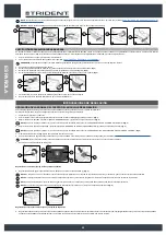
SOLICITUD AUTOMÁTICA DE ASISTENCIA TÉCNICA (VERSIONES HFM)
La máquina tiene un servicio automático para solicitar urgente asistencia técnica. Para activar dicha función el operador debe presionar el pulsador (2) ubicado debajo de la
puerta (1) que tiene el símbolo de “SOS” (
Fig.1
).
NOTA
: para poder activar el servicio automático de asistencia técnica, la máquina debe estar equipada con el kit HILLYARD FLEET MANAGEMENT.
NOTA
: Para poder enviar el mensaje de asistencia técnica, la máquina debe estar encendida y encontrarse en una zona donde sea posible la transmisión de datos.
1
1
2
SISTEMA AUTOMÁTICO DE DOSIFICACIÓN DEL DETERGENTE (VERSIONES HDC)
Opcionalmente, se puede instalar en la máquina un sistema que permite dosificar por separado el detergente con el agua del tanque solución.
Para activarlo efectuar las siguientes operaciones.
1.
Con la máquina activa presionar el pulsador “ACTIVACIÓN - DESACTIVACIÓN DEL SISTEMA HDC” (1) (
Fig.1
).
NOTA
: si el led del pulsador (1) está encendido, el sistema HDC está activo, de lo contrario, el sistema HDC está desactivado.
NOTA
: el sistema HDC se activará al activarse la bomba eléctrica de la instalación hídrica de la máquina.
NOTA
: para desactivar el sistema HDC, presionar nuevamente el pulsador (2).
NOTA
: la cantidad de detergente presente en la solución de lavado que suministra la máquina es proporcional (en un porcentaje definido por un parámetro preestablecido
en la máquina) al caudal de agua existente en el circuito hídrico de la máquina.
1
1
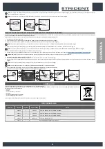
PULSADOR DE EMERGENCIA
Si durante el trabajo surgieran graves problemas de seguridad, presionar el pulsador de emergencia (1) ubicado sobre el cárter que cubre la instalación eléctrica (
Fig. 1
).
PRUDENCIA
: Este mando interrumpe el circuito eléctrico que va desde las baterías a la instalación de la máquina.
NOTA
: para reanudar el trabajo una vez que se ha detenido la máquina y se ha resuelto el problema:
•
Colocar el interruptor general en posición “0” (
Fig.2
).
•
Desplazar hacia adelante el pulsador de emergencia (1) (
Fig. 3
).
•
Colocar el interruptor general en la posición “I” (
Fig.4
).
1
3
1
1
2
4
2
2
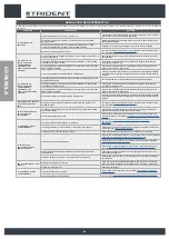
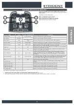
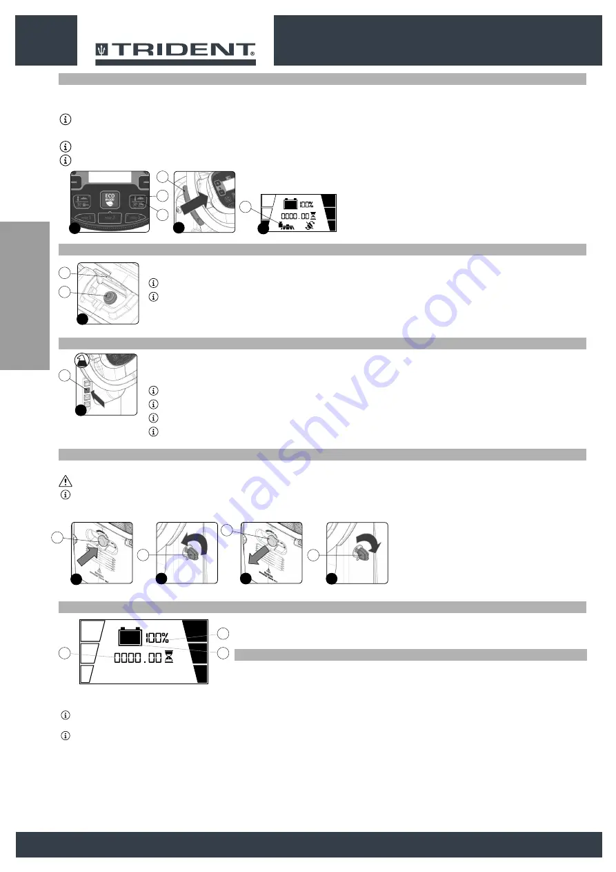
CONTADOR DE HORAS
En el panel de mando de la máquina hay una pantalla de control que permite observar el tiempo total de uso mediante una serie de
números (1). Las cifras seguidas de la letra “h” identifican las horas, mientras que las cifras seguidas de la letra “m” identifican los
decimales de hora (un decimal de hora corresponde a seis minutos). Cuando parpadea el símbolo “:” significa que el contador de horas
está contando el tiempo de funcionamiento de la máquina.
INDICADOR DEL NIVEL DE CARGA DE LAS BATERÍAS
En el panel de mandos se encuentra la pantalla de control en cuya parte central se puede ver el nivel de carga de las baterías.
El indicador tiene dos símbolos de nivel de carga: el primero está representado por el símbolo gráfico (2) y el segundo por un número que
indica el porcentaje de carga (3).
La indicación se compone de 5 niveles de carga, cada uno de los cuales representa aproximadamente el 20% de carga residual. Con una
carga restante del 20 %, el símbolo gráfico comenzará a parpadear y, después de pocos segundos, se mostrará con un tamaño más grande
en el centro de la pantalla. En este caso llevar la máquina al lugar específico para la recarga de las baterías
NOTA
: Algunos segundos después de que la carga de las baterías llega al 20%, el motor del cepillo se apaga automáticamente. Con la carga residual es posible, de todas maneras, acabar el trabajo de
secado antes de efectuar la carga
NOTA
: Algunos segundos después de que la carga de las baterías llega al 10%, el motor aspiración se apaga automáticamente. Sin embargo es posible, con la carga restante, desplazar la máquina hasta
un lugar dispuesto para la recarga.
3
2
1
44
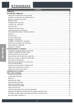
Summary of Contents for TRIDENT R26SC PRO
Page 2: ......
Page 3: ...ENGLISH 4 ESPA OLA 30 FRAN AIS 56 3 ESPA OLA FRAN AIS ENGLISH...
Page 82: ...ESPA OLA FRAN AIS ENGLISH 82...
Page 83: ......


