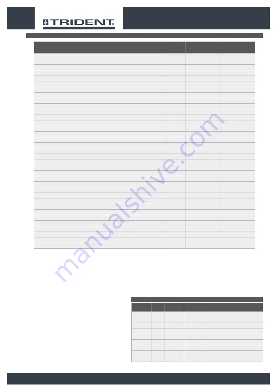
background image

TECHNICAL DATA

Remarks:

(1) Machine weight: refers to the overall weight of the machine; without the battery box; with no 

operator on board, and with both tanks empty.

(2) Machine weight during transport: refers to the overall weight of the machine; with the battery 

box inserted; with no operator on board, and with both tanks empty.

(3) Machine weight during work operations: refers to the overall weight of the machine; with the 

battery box inserted; with addition of 70kg operator on-board; with the solution tank full; with 

the detergent canister full; with the safety kit fitted.
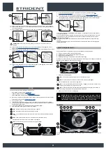
BRUSH TYPE

CODE

QTY

Ø


EXTERNAL

TYPE OF 

BRISTLE

NOTES

447244

2

Ø18in

PPL Ø0.6

WHITE CENTRAL BRUSH

447246

2

Ø18in

PPL Ø0.9

BLACK CENTRAL BRUSH

447248

2

Ø18in

ABRASIVE

CENTRAL BRUSH

447251

2

Ø18in

-

CENTRAL PAD HOLDER

427709

1

Ø18in

PPL Ø0.3

BLUE SIDE BRUSH

427710

1

Ø18in

PPL Ø0.6

WHITE SIDE BRUSH

427711

1

Ø18in

PPL Ø0.9

BLACK SIDE BRUSH

427712

1

Ø11in

ABRASIVE

SIDE BRUSH

427713

1

Ø11in

-

SIDE PAD HOLDER

12

TECHNICAL DATA

SI

[KMS]

TRIDENT R36 

SC PLUS

TRIDENT R36 

SC 1SL PLUS

Rated machine power

W

3050

3250

Working capacity up to 

ft

2

/h

58125

58125

Working width

in

35.4

35.4

Working width with the lateral brush

in

-

41.3

Squeegee width

in

41.1

41.1

Central brush head brushes (number -Ø external bristles)

Nº - in

2 - Ø18.1

2 - Ø18.1

Central brush head motor (voltage - nominal power rating)

V - W

36 - 750

36 - 750

Rpm of the individual brush on the central brush head

rpm

180

180

Lateral brush head unit motor (voltage - nominal power rating)

V - W

-

36 - 200

Lateral brush head brush rotations

rpm

-

140

Side brushes (number -Ø external bristles)

Nº - in

-

1 - Ø11.4

Lateral brush head unit lateral movement

in

-

2.5

Maximum weight exerted upon the central brush head

lb

331

331

Maximum weight exerted upon the lateral brush head

lb

-

22

Traction motor (voltage / rated power)

V - W

36 - 900

36 - 900

Maximum negotiable slope (“transport” working program and empty tanks)

%

18

18

Maximum speed (with transport program)

mph

5.6

5.6

Vacuum motor (voltage - nominal power rating)

V - W

36 - 650

36 - 650

Vacuum head vacuum (versions with one motor - versions with two motors)

PSI

(2.76 - )

(2.76 - )

Wand kit vacuum

PSI

-

-

Maximum solution tank capacity

gal

50

50

Maximum recovery tank capacity

gal

53

53

Maximum capacity of the detergent canister (versions with automatic detergent dosing system)

gal

4

4

Turning circle (without front bumpers it and without roof)

in

38.8

38.8

Machine dimensions (length - width - height)

in

72.4 - 42.7 - 54.1

72.4 - 42.7 - 54.1

Machine dimensions with front bumpers kit and roof  (length - width - height)

in

74.6 - 42.7 - 76.8

74.6 - 42.7 - 76.8

Battery compartment dimensions (length - width - useful height)

in

37.8 - 15.7 - 19.9

37.8 - 15.7 - 19.9

Machine weight

(1)

lb

992

1003

Machine weight during transport

(2)

lb

1909

871

Machine weight during work operations

(3)

lb

2657

1920

Weight of the front bumpers kit and roof

lb

139

139

Maximum weight of the battery box (recommended)

lb

917

917

Sound pressure level (ISO 11201) - L

pa

dB(A)

< 70

< 70

Uncertainty K

pa

dB(A)

1.5

1.5

Body vibration level (ISO 2631) 

m/s

2

0.5

0.5

Summary of Contents for TRIDENT R36 SC 1SL PLUS

Page 1: ...Instructions originales DOC 10076229 Ver AA 06 2018 Scrubbing machine Use and Maintenance manual...

Page 2: ......

Page 3: ...e vacuum hose 16 Squeegee body 17 Command display 18 Brush head extra pressure selection lever 19 Horn button 20 Detergent solution tap control lever 21 Steering wheel 22 Reverse gear selection lever...

Page 4: ...CLING SYSTEM OPTIONAL 24 AUTOMATIC REQUEST FOR TECHNICAL ASSISTANCE OPTIONAL 24 AUTOMATIC DETERGENT DOSING SYSTEM OPTIONAL 24 TUTORIAL 25 REAR VIDEO CAMERA OPTIONAL 25 EMERGENCY BUTTON 25 HOUR METER 2...

Page 5: ...S DANGER If the battery charger power cable is damaged or broken it should be replaced by the manufacturer by authorised service personnel or else by a qualified person in order to protect against haz...

Page 6: ...ould not be done by unsupervised children In the event of danger take prompt action by pressing the emergency button near the operator s seat Never collect gases explosive inflammable liquids or powde...

Page 7: ...the machine only in the way described in this manual Do not pick up anything that is burning or smouldering like cigarettes matches or glowing embers Reduce speed on slopes and dangerous corners Redu...

Page 8: ...work check that all the safety devices have been installed and are working correctly Take all due precautions so that hair jewellery loose clothing do not get entangled in the machine s moving parts...

Page 9: ...ATTENTION Never tamper with the machine s protection devices for any reason always follow the supplied routine maintenance instructions scrupulously The electro magnetic brake must be released in ord...

Page 10: ...be carried out by qualified personnel Do not physically change the design characteristics of the machine Use spare parts supplied by HILLYARD or by HILLYARD service centres Wear personal protective e...

Page 11: ...onsible for machine operation The majority of occupational accidents that happen either in the workplace or whilst moving are caused by failure to respect the most basic safety rules An attentive care...

Page 12: ...ntral brush head rpm 180 180 Lateral brush head unit motor voltage nominal power rating V W 36 200 Lateral brush head brush rotations rpm 140 Side brushes number external bristles N in 1 11 4 Lateral...

Page 13: ...e nominal power rating V W 36 90 Lateral brush head brush rotations rpm 75 Side brushes number external bristles N in 2 17 7 Maximum weight exerted upon the central brush head lb 132 132 Maximum weigh...

Page 14: ...e indicates that the tank is full Main switch symbol Applied to the control panel positioned on the front of the machine to indicate the main switch Acoustic signalling device control label Applied in...

Page 15: ...Check that the main switch on the control panel has been set to 0 If this is not the case turn the key 2 a quarter turn anti clockwise Fig 2 Remove the key from the main switch 7 Grip the back of the...

Page 16: ...head and the squeegee support will be in the resting position raised from the floor N B in the DS selector the symbol of the transport program 1 is green Fig 1 N B the grey symbols show working progra...

Page 17: ...through contact with it ATTENTION the room used to recharge the batteries must be adequately ventilated to prevent the accumulation of gases that leak from batteries 3 Get off the machine CAUTION when...

Page 18: ...wer than the shoulders With a good grip on the steering wheel the elbows should be bent by about 120 They should be at least 30 cm between the middle of the steering wheel and our breastbone In any ca...

Page 19: ...1 Make sure the recovery tank is empty If this is not the case empty it read EMPTYING THE RECOVERY TANK 2 Check that the amount of detergent solution present in the solution tank is sufficient for th...

Page 20: ...ired work area and press the ZONE key see ZONE PROGRAM MODE 10 If a working program is selected which includes SCRUBBING WITH DRYING open the flow of the detergent solution into the machine s water sy...

Page 21: ...rush head motors stop with the respective delays After the Reset Delay time all the brush heads are taken to the rest position raised off the floor by pressing the forward movement pedal it will start...

Page 22: ...rs that were set before it stopped N B if you reverse with this program active the brush head will remain in contact with the floor the motor will continue working but the solenoid valve will not deli...

Page 23: ...essure exercised on the central brush head and performance level of the vacuum motor N B the disabled buttons and the respective indicators are grey N B each time one of the enabled keys is pressed it...

Page 24: ...ith a system that allows the detergent solution to be recycled so that productivity can be increased since the number of stops needed to empty and fill the tanks is reduced As a result less water and...

Page 25: ...ed as follows 1 On any screen press the VIDEO CAMERA button 1 Fig 1 2 As soon as the button 1 is pressed the video camera image is shown full screen N B to exit the video camera screen press on any po...

Page 26: ...nnect the vacuum tube 4 to the extension tube 3 Fig 4 2 3 Back 0000 00 100 1 1 5 Insert the vacuum brush 5 in the extension tube 3 Fig 5 6 Remove the vacuum tube 6 from the sleeve 7 in the squeegee bo...

Page 27: ...careful cleaning of the whole vacuum unit ensures better drying and cleaning of the floor as well as a longer vacuum motor life To carry out the cleaning of the squeegee body proceed as follows 1 Take...

Page 28: ...lace 8 Clean the brush under a stream of running water to remove any impurities from its bristles Check the wear status of the bristles and replace the brushes if they are excessively consumed the bri...

Page 29: ...8 Activate the optional tank cleaning kit ON OFF pump by pressing the button 6 on the back of the machine Fig 7 CAUTION when using the optional tank cleaning kit you are advised to always wear goggles...

Page 30: ...see the section titled SECURING THE MACHINE CAUTION these operations must be carried out using protective gloves to avoid any possible contact with the edges or tips of metal objects 3 Stand on the r...

Page 31: ...ssory itself Fig 8 N B to stop the solution jet use the lever 10 on the tank cleaning accessory Fig 9 5 6 7 6 8 4 5 7 DRIVE 0000 00 100 3 1 2 2 3 4 1 4 5 6 5 6 7 9 Remove the dirty water basket filter...

Page 32: ...ure the machine has been secured see the section titled SECURING THE MACHINE CAUTION users are advised to always wear protective gloves to avoid the risk of serious injury to hands 3 Close the tap s o...

Page 33: ...tled SECURING THE MACHINE ATTENTION users are advised to always wear protective gloves to avoid the risk of serious injury to hands 3 Extract the vacuum tube 1 from the vacuum nozzle on the squeegee b...

Page 34: ...OIL BASIN If a braking system anomaly alarm is activated when you are working quickly stop the machine and check the oil level in the machine s brake system To check and top up the oil in the braking...

Page 35: ...ot do their work properly namely convey the dirty detergent solution towards the squeegee therefore the height of the splashguard needs to be adjusted This operation can be done with the brush head bo...

Page 36: ...ing insert the retainer 8 into the slot 9 Fig 8 10 Disconnect the battery connector from the machine s main system connector Fig 9 11 Grip the back of the seat 7 and turn the seat support plate to the...

Page 37: ...l check the meaning of the flashing signals that the battery charger emits dung the battery recharge stage THE MACHINE HAS A VERY LOW WORK AUTONOMY Check the battery charge level check the symbol on t...

Page 38: ...4 Esci ZONE MANUAL ON OFF Programmazione Zone Zone 1 Zone 2 Zone 3 Zone 4 Esci ZONE MANUAL ON Monitor General Brush Pump Vacuum Traction Esci Valore 1 100 Valore 2 23 5 Valore 3 Valore 4 A V OFF ON P...

Page 39: ...Programmazione Zone Parametri Monitor Allarmi Esci VISUALIZZATO TOTALE PARZIALE Chiave 0000 00 0000 00 Trazione 0000 00 0000 00 Spazzole 0000 00 0000 00 Aspirazione 0000 00 0000 00 Chiave 3 4 3 5 4 R...

Page 40: ...ress the menu button 1 on the working screen Fig 1 2 Press the setting 2 Fig 2 3 In the MAIN MENU screen select the ZONE PROGRAMMING option 3 on the left hand side of the screen Fig 3 N B when the but...

Page 41: ...EXIT key Reset Menu principale Lingua Contaore Programmazione Zone Parametri Monitor Allarmi Esci VISUALIZZATO TOTALE PARZIALE Chiave 0000 00 0000 00 Trazione 0000 00 0000 00 Spazzole 0000 00 0000 00...

Page 42: ...immediate stopping of the entire machine or a part of it ALARM NUMBER DESCRIPTION AL_12 General Update in progress AL_15 General Brake fluid reserve AL_46 Function Overcurrent Outputs Brushes 1 2 3 A...

Page 43: ......

Page 44: ...HILLYARD INDUSTRIES PO Box 909 St Joseph Missouri 64502 0909 U S A Telephone 816 233 1321 www hillyard com...

Reviews: