


26.
For reasons of packaging, the splashguards are supplied not fitted on the machine, to fit
them to the brush head body read the paragraph “
FITTING THE BRUSH HEAD BODY SIDE
SPLASHGUARDS (WASHING VERSION)
”.
27. For reasons of packaging, if the machine version provides for it, the side brush is supplied not
fitted on the machine, to fit it to the side brush head body read the paragraph “
HOW TO MOVE THE MACHINE
To transport the machine safely, proceed as follows:
DANGER
: before starting any task, make sure the current regulations concerning the safe
transport of dangerous substances are scrupulously observed.
1. Check to make sure that the solution tank and the recovery tank are empty. If this is not the case,
empty them (see the sections titled “
2. Sit on the driver’s seat.
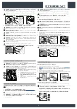
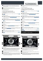
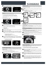
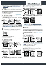
3. Insert the key (1) into the main switch on the control panel. Set the main switch to "I" (
Fig.1
).
4. Using the DS selector on the control display (
Fig.2
), select the “transfer” program (2).
N.B.
: in this working program both the brush head and the squeegee support will be in the
resting position (raised from the floor).
N.B.
: in the DS selector the transport program symbol (2) is green (
Fig.2
).
N.B.
: the grey symbols show working programs that are not active. the green symbols show
working programs that are active.
5. Press the drive pedal (3) (
Fig.3
) to begin moving the machine.
6. Use a ramp to move the machine up onto the transport vehicle.
CAUTION
: during this operation, check there are no people or objects near the machine.
N.B.
: the ramp gradient must not be such as to cause damage to the machine as it goes up.
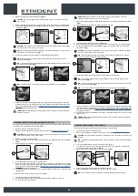
7. Once the machine is on the transport vehicle, set the main switch to “0” (
Fig. 4
). Remove the key
from the main switch.
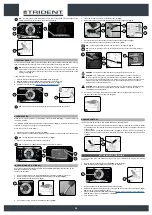
8.
Get off the machine.
CAUTION
: when getting down from the machine, do not place your foot on the scrubbing brush
head or side brush head brush.
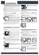
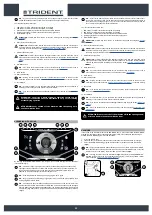
9. Grip the back of the seat (4) and turn the seat support plate to its maintenance position (
Fig.5
).
ATTENTION:
to prevent the seat from rotating, insert the retainer (5) into the slot (6) (
Fig.6
).
10. Disconnect the battery connector from the machine's main system connector (
Fig.7
).
11. Grip the back of the seat (4) and turn the seat support plate to the working position.
N.B.
: before rotating the seat support plate, remove the retainer (5).
WARNING
: secure the device according to the directives in force in the country of use, so that it
cannot slide or tip over.
1
1
ON
3
3
DRIVE
0000.00
100%
2
2
5
6
4
6
5
4
1
OFF
7
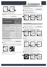
MACHINE SAFETY
To ensure that work is carried out in the best safety conditions, proceed as follows:
1. Make sure the solution tank is empty. If this is not the case, empty it (read "
2. Make sure the recovery tank is empty. If this is not the case, empty it (read "
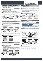
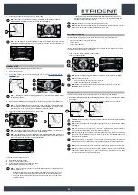
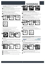
3. Using the DS selector on the control display (
Fig.1
), select the “transfer” program” (1).
N.B.
: in this working program both the brush head and the squeegee support will be in the
resting position (raised from the floor).
N.B.
: in the DS selector the symbol of the transport program (1) is green (
Fig.1
).
N.B.
: the grey symbols show working programs that are not active. the green symbols show
working programs that are active.
4. Set the main machine switch to “0” (
Fig.2
). Remove the key from the instrument panel.
5.
Get off the machine.
CAUTION
: when getting down from the machine, do not place your foot on the scrubbing brush
head or side brush head brush.
6. Grip the back of the seat (3) and turn the seat support plate to its maintenance position (
Fig.3
).
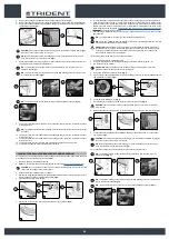
ATTENTION:
to prevent the seat from rotating, insert the retainer (4) into the slot (5) (
Fig.4
).
7. Disconnect the battery connector from the machine's main system connector (
Fig.5
).
8. Grip the back of the seat (3) and turn the seat support plate to the working position.
N.B.
: before rotating the seat support plate, remove the retainer (4).
3
3
2
2
OFF
DRIVE
0000.00
100%
1
1
4
4
5
5
BATTERY MAINTENANCE AND DISPOSAL
For battery maintenance and recharging, respect the instructions provided by the battery manufacturer.
When the batteries reach the end of their service life, they must be disconnected by specialized and
properly trained personnel, and must be subsequently removed from the battery compartment using
suitable lifting devices.
N.B.
: dead batteries are classified as dangerous waste and as such must be delivered to an
authorised body for disposal.
INSERTING THE BATTERIES INTO THE MACHINE
The batteries must be housed in the special compartment beneath the recovery tank and should be
handled using lifting equipment that is suitable in terms of both weight and its coupling system.
DANGER
: make sure that you comply with the accident prevention regulations in force in the
country where you work or with DIN EN 50272-3 and DIN EN 50110-1, before any handling of
the batteries.
CAUTION
: to prevent an accidental short circuit use insulated tools to connect the batteries, and
do not place or drop metal objects on the battery. Remove rings, watches and any clothing with
metal parts that may come into contact with the battery terminals.
The various phases for inserting the batteries in the battery compartment are as follows:
1. Make sure the solution tank is empty. If this is not the case, empty it (read "
").
2. Make sure the recovery tank is empty. If this is not the case, empty it (read "
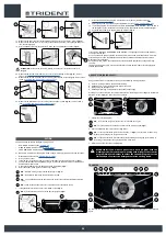
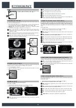
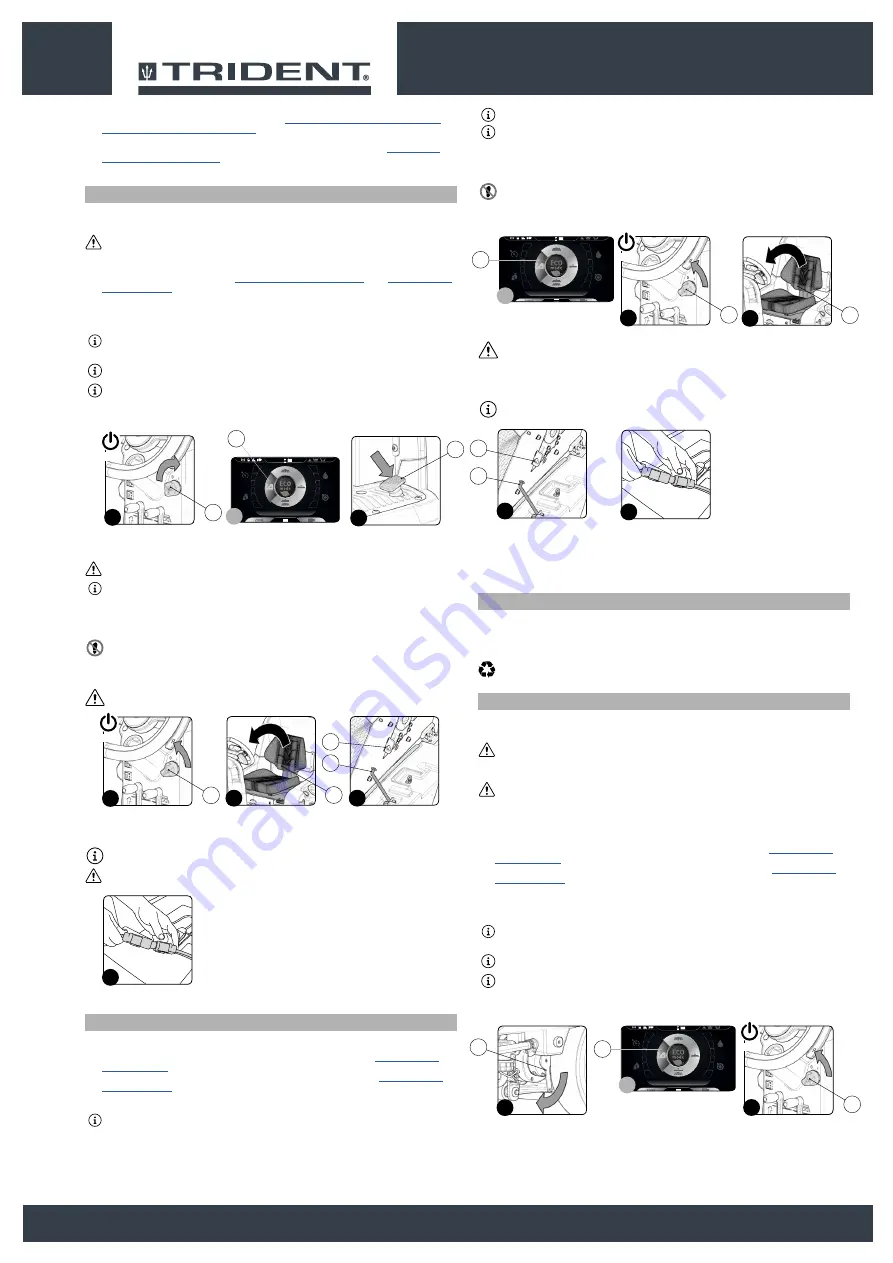
3. Make sure the electronic brake is engaged. If this is not the case, turn the lever (1) clockwise. The
traction gear motor is located on the rear left-hand side of the machine (
Fig.1
)
4. Using the DS selector on the control display (
Fig.2
), select the “transfer” program (2).
N.B.
: in this working program both the brush head and the squeegee support will be in the
resting position (raised from the floor).
N.B.
: in the DS selector the transport program symbol (2) is green (
Fig.2
).
N.B.
: the grey symbols show working programs that are not active. the green symbols show
working programs that are active.
5. Set the main switch to “0” (
Fig.3
). Remove the key from the instrument panel.
6.
Get off the machine.
3
3
OFF
DRIVE
0000.00
100%
2
2
1
1
16


