


WORK
The machine can be used in the following work modes:
•
ECO-MODE, read the section “
”;
•
MANUAL MODE, read the section “
•
PROGRAM ZONE, read the section “
”.
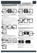
As an example, we will look at the program mode. To begin working in this mode, proceed as follows:
1. Make all the checks listed in “
”.
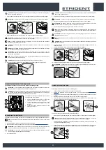
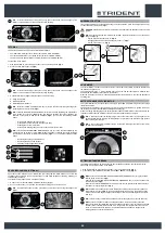
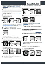
2. Sit on the driver’s seat.
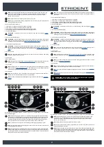
3. Insert the key (1) into the main switch on the control panel. Set the main switch to "I" (
Fig.1
).
4.
The first and second screen displayed allow you to check the software versions of the functions
board and the display board.
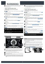
5. A few seconds after ignition, the password screen is displayed (
Fig.2
).
6. Enter the password and press the enter key (2) (
Fig. 2
).
N.B.
: to delete a wrong entry press the delete key (3) (
Fig. 2
).
N.B.
: the password entered by the manufacturer is 1000.
N.B.
: it is possible to disable the password entry, contact the nearest HILLYARD assistance
centre.
N.B.
: to find out the password to enter, contact the nearest assistance centre.
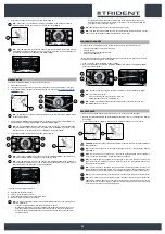
7. If the password is correct you pass to the “MAIN” screen (
Fig.3
).
N.B.
: by default the machine is set to the transfer program (
Fig.3
).
1
Enter
Inserire codice
DRIVE
0000.00
100%
2
3
1
3
2
ON
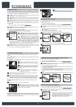
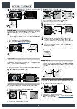
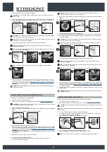
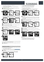
17. Make sure the cap of the recovery tank drainage tube (10) is closed. If it isn't, close it (
Fig.10
).
18. Make sure the vacuum tube (11) is correctly connected to the sleeve in the squeegee body. If it
isn't, connect it (
Fig.11
).
19. Grip the handle (12) and raise the recovery tank's lid to its maintenance position (
Fig.12
).
ATTENTION:
to prevent the cover from rotating, insert the pin (13) into the support (14)
(
Fig.13
).
20.
Make sure the vacuum motor filter (15) is correctly connected and is clean (
Fig.14
). If it isn't,
clean it (see “
CLEANING THE RECOVERY TANK FILTERS
21.
Make sure the vacuum duct filter (15) is correctly connected and is clean (
Fig.15
). If it isn't, clean
it (see “
CLEANING THE RECOVERY TANK FILTERS
22.
Make sure the filter-strainer (17) is correctly connected and is clean (
Fig.16
). If it isn't, clean it
CLEANING THE RECOVERY TANK FILTERS
”).
8
9
7
8
7
9
11
12
10
10
11
12
14
15
13
14
13
15
16
16
17
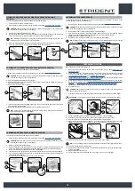
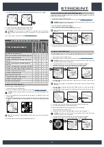
8. Select the desired working program with the DS selector device (read the section “
”).
9. Select the required work area and press the “ZONE” key (see “
”).
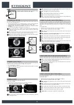
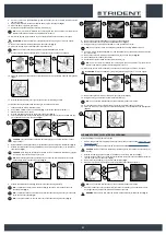
10.
If a working program is selected which includes “SCRUBBING WITH DRYING”, open the flow of
the detergent solution into the machine's water system and shift the knob (4) upwards (
Fig. 4
).
11. Press the drive pedal (5) to begin moving the machine (
Fig. 5
).
If the program selected is “SCRUBBING WITH DRYING”, the squeegee and brush head will lower
until they touch the floor.
As soon as the drive pedal is pressed, the traction motor, brush head motor and vacuum motor will
start working. As a result, the solenoid valve will also be activated and detergent solution will be
dispensed onto the brushes.
During the first few metres, check that there is sufficient solution and that the squeegee is drying
correctly.
The machine will now begin to work with full efficiency until the battery is flat or until the detergent
solution has finished.
5
4
4
5
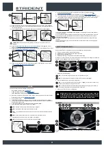
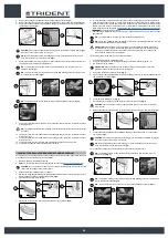
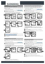
DS SELECTOR (DRIVE SELECT)
Using the DS selector it is possible to select one of the following working programs:
A. Transfer: movement of the machine without working.
B. Scrubbing only : using only the brushes in the brush head.
C. Drying: using the squeegee only.
D. Scrubbing with Drying: using both the brushes and the squeegee.
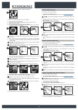
Pressing one of the symbols in the selector will shift from the working screen (
Fig.1
) to the “DRIVE
SELECT” screen (
Fig.2
). On this screen it is possible to:
DRIVE
0000.00
100%
Back
0000.00
100%
A
B
D
C
1
1
2
1.
Confirm the selected program.
N.B.
: to confirm the program press the icon just selected once again.
N.B.
: once the selection is confirmed you return to the working screen (
Fig.1
).
2. Cancel the selection and return to the working screen
N.B.
: to cancel the selection press the “back” button (1) (
Fig.2
) and you return to the working
screen without changing the program being used.
N.B.
: to cancel the selection wait 5 seconds without selecting anything and you will return to
the working screen without changing the program being used.
3. Select a mode other than the one highlighted.
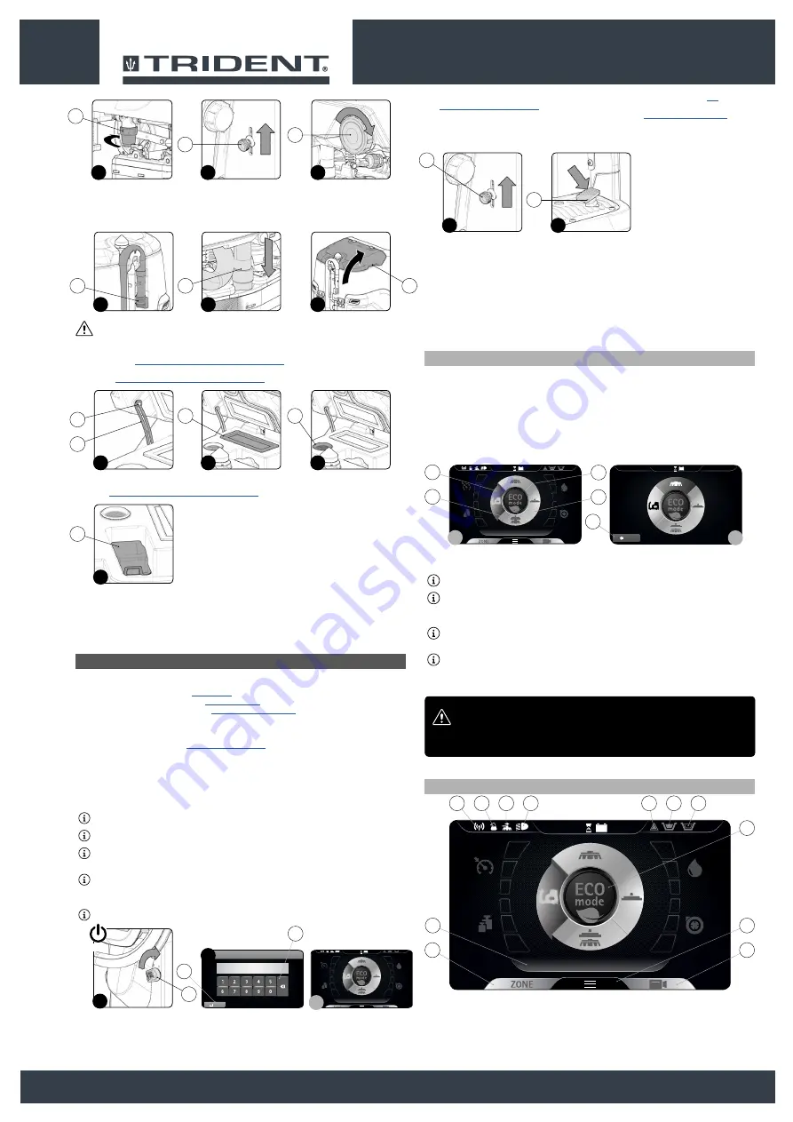
ATTENTION: if you want to pass from a work program with the
washing mode (only washing or washing with drying) to the transfer
program always remember to select the vacuum program for the
time needed to collect the detergent solution on the ground.
TRANSFER
DRIVE
0000.00
100%
9
12
8
10
11
1
5
2
6
3
7
4
By selecting the "TRANSFER” program, the command display screen will appear as in the adjacent
figure.
20


