

ADJUSTMENT INTERVENTIONS
ADJUSTING THE SQUEEGEE BODY'S RUBBER BLADES
The careful adjustment of the squeegee body rubber blades guarantees better cleaning of the floor.
To adjust the squeegee body blades, proceed as follows:
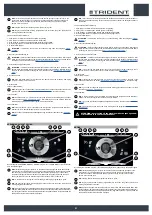
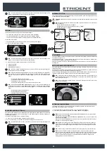
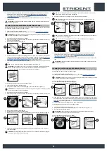
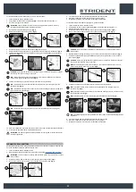
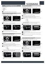
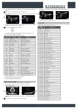
1. Sit on the driver’s seat.
2. Insert the key (1) into the main switch on the control panel. Set the main switch to "I" (
Fig.1
).
3. Using the DS selector, select the SCRUBBING WITH DRYING mode (2) (
Fig. 2
).
4. Press the drive pedal (3) (
Fig.3
) to begin moving the machine.
5. As soon as the brush head and the squeegee have reached their working positions, perform the
procedure for securing the machine (see the section titled “
ATTENTION
: these operations must be carried out using protective gloves to avoid any possible
contact with the edges or tips of metal objects.
6. Stand at the back of the machine.
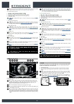
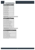
Adjusting the height of the squeegee body:
7. Release the stopper lever (4) for the squeegee's height adjustment knob (5) (
Fig.4
).
8.
Adjust the height of the rubber blade in relation to the floor by loosening or tightening the knobs
(5) (
Fig.5
).
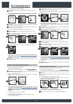
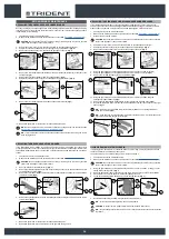
N.B.
: Figure 5 indicates the direction of rotation for decreasing the distance between the
squeegee support and the floor. This distance can be increased by turning it in the opposite
direction.
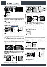
N.B.
: By decreasing the distance between the squeegee support and the floor, the rubber blades
present in the squeegee's body move closer to the floor.
N.B.
: the right-hand and left-hand knobs must be rotated the same number of times, so that the
squeegee is parallel to the floor when it is working.
N.B.
: Check for proper adjustment by looking at the instrument (6) positioned on the squeegee
body (
Fig.6
).
9. Once the adjustment has been completed, engage the stopper lever (4) (
Fig.7
).
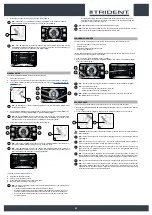
Adjusting the tilt of the squeegee body:
10. Loosen the stopper knob (7) for the squeegee's tilt adjustment knob (8) (
Fig.8
).
11.
Adjust the tilt of the squeegee body's rubber blades in relation to the floor, tighten or loosen
the knob (8) (
Fig.9
) until the squeegee body's rubber blades are bent outwards by about 30° in
relation to the floor, in an even manner along their entire length.
N.B.
: Figure 9 indicates the direction of rotation for tilting the squeegee towards the rear of the
machine (
Fig.10
). Turn it in the opposite direction to rotate the squeegee towards the front of the
machine.
N.B.
: Check for proper adjustment by looking at the instrument (9) positioned on the squeegee
body (
Fig.6
).
12. Once the adjustment has been completed, tighten the stopper knob (7) (
Fig.11
).
3
1
1
3
OFFICE
0000.00
100%
2
2
5
6
4
4
5
5
6
9
7
4
9
10
8
8
8
7
11
7
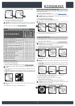
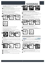
ADJUSTING BRUSH HEAD BODY SIDE SPLASHGUARDS
If the side splashguards of the brush head body are not positioned correctly they cannot do their work
properly, namely convey the dirty detergent solution towards the squeegee, therefore the height of the
splashguard needs to be adjusted.
This operation can be done with the brush head body in the work position, proceeding as follows:
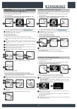
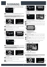
1. Sit on the driver’s seat.
2. Insert the key (1) into the main switch on the control panel. Set the main switch to "I" (
Fig.1
).
3. Using the DS selector, select the SCRUBBING WITH DRYING mode (2) (
Fig. 2
).
4. Press the drive pedal (3) (
Fig.3
) to begin moving the machine.
5. As soon as the brush head and the squeegee have reached their working positions, perform the
procedure for securing the machine (see the section titled “
”).
ATTENTION
: these operations must be carried out using protective gloves to avoid any possible
contact with the edges or tips of metal objects.
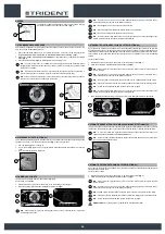
6. Go to the front left-hand side of the machine.
7. Open the machine's left lateral casing (4) (
Fig.4
).
8. Loosen the retention nuts (5) of the adjusting screws (6) (
Fig.5
).
9.
Adjust the height of the splashguard with respect to the floor, tighten or loosen the screws (6)
until the splashguard touches the floor along its entire length (
Fig.6
).
N.B.
: Both the front and rear of the splashguard need to be at the same height off the floor.
10. Once the adjustment has been completed, tighten the retention nuts (5).
11. Close the left lateral carter (4).
12. Repeat the operations just carried out also for the right side splashguard as well.
3
1
1
3
OFFICE
0000.00
100%
2
2
6
4
5
4
6
5
6
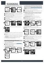
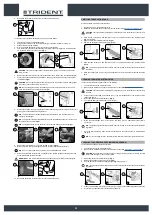
ADJUSTING THE SIDE BRUSH (SWEEPING VERSION)
If the side brush does not channel the dirt efficiently towards the centre of the machine, you must adjust
its height in relation to the ground, as follows:
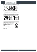
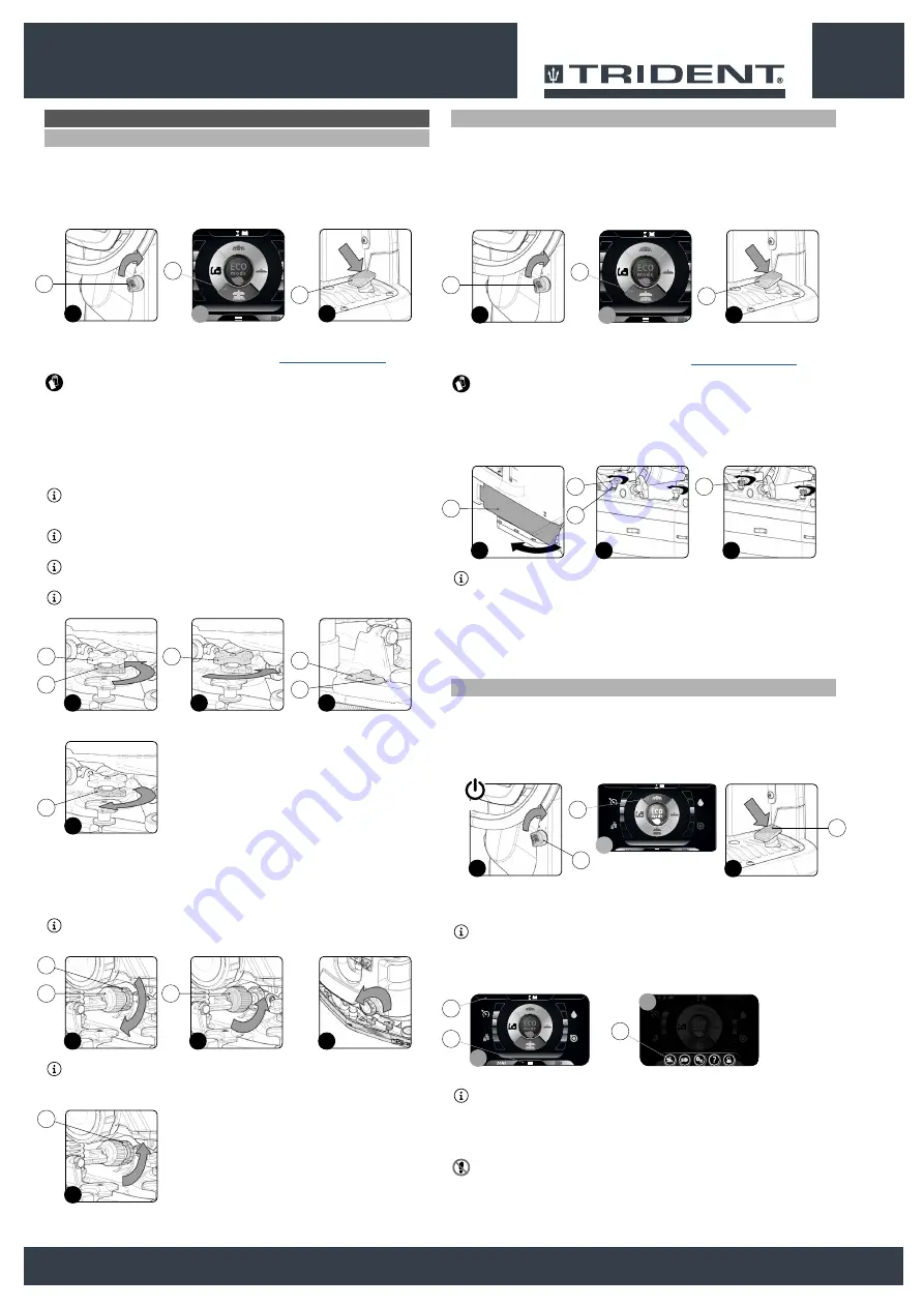
1. Sit on the driver’s seat.
2. Insert the key (1) into the main switch on the control panel. Set the main switch to "I" (
Fig.1
).
3. Using the DS selector, select the PRE-SCRUBBING mode (2) (
Fig. 2
).
4. Press the drive pedal (3) (
Fig.3
) to begin moving the machine.
5. With the machine on, press the menu button (4) on the working screen (
Fig.4
).
6. Press the ACTIVATING-DEACTIVATING THE SIDE BRUSH button (5) (
Fig.5
).
N.B.
: when the key
ACTIVATING-DEACTIVATING THE SIDE BRUSH (5)
is grey it shows that
the brush is not active
(
Fig.5
)
.
when the key
ACTIVATING-DEACTIVATING THE SIDE BRUSH (5)
is green it shows that the
brush is active
(
Fig.5
)
.
Moreover, when the
SIDE BRUSH
mode is active, the top left part of the work screen displays
the symbol (6) specifically for this (
Fig.4
).
N.B.
: the side brush head starts to move towards the outside of the machine only when the
drive pedal (3) is pressed (
Fig.3
).
7.
As soon as the side brush is in contact with the floor, set the main switch to “0” (
Fig.6
). Remove
the key from the instrument panel.
8.
Get off the machine.
CAUTION
: when getting down from the machine, do not place your foot on the scrubbing brush
head or side brush head brush.
1
ECO mode
0000.00
100%
2
1
2
ON
3
3
OFFICE
0000.00
100%
0000.00
100%
ECO mode
4
5
5
4
3
35


