


DETERGENT SOLUTION
For the versions without automatic detergent dosing system, after filling the solution tank with clean
water, add the liquid detergent to the tank in the concentration and manner indicated on the detergent
manufacturer's label. To prevent the formation of an excessive amount of foam that could damage the
vacuum motor, use the minimum percentage of detergent required.
CAUTION
: protective gloves should always be worn before handling detergents or acidic or
alkaline solutions, to avoid serious injury to the hands.
ATTENTION
: always use detergents whose manufacturer's label indicates their suitability for
scrubbing machines. Do not use acid or alkaline products or solvents without this indication.
ATTENTION
: always use low-foam detergent. To avoid the production of foam, put a minimum
quantity of anti-foam liquid in the recovery tank before starting to clean. Do not use pure acids.
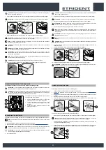
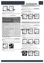
For versions with automatic detergent dosing system, fill the solution tank with clean water and then
proceed as follows:
1. Make sure the machine is in a safe condition (read “
CAUTION
: protective gloves should always be worn before handling detergents or acidic or
alkaline solutions, to avoid serious injury to the hands.
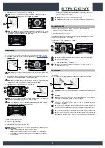
2. Remove the cap (1) of the detergent canister (
Fig.1
).
3. Fill the canister with the desired detergent; it is possible to see the quantity ion the detergent
canister using the level tube (2) on the front left of the canister (
Fig. 1
).
ATTENTION
: always use detergents whose manufacturer's
label indicates their suitability for scrubbing machines. Do
not use acid or alkaline products or solvents without this indication.
ATTENTION
: the dosing system is suitable for frequent
maintenance cleaning. Acid or alkaline maintenance
detergent tank be used with pH values between 4 and 10
and that do not contain: oxidising agents, chlorine or bromine,
formaldehyde, mineral solvents. The detergents used must be suitable
for use with scrubbing machines. Wash the circuit with water after use
if the system is not used daily. The system can be excluded. In case of sporadic use of
detergents with pH between 1-3 or 11-14, use the floor scrubbing machine in the traditional way
by adding the detergent in the clean water tank and excluding the dosing circuit.
ATTENTION
: always use low-foam detergent. To avoid the production of foam, put a minimum
quantity of anti-foam liquid in the recovery tank before starting to clean. Do not use pure acids.
4. Close the cap (1) correctly to prevent liquid coming out when working.
1
2
1
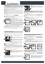
ADJUSTMENT OF DRIVING POSITION
The proper adjustment of the driving position provides a greater sense of comfort when using the
machine.
Correct position on the seat
: make sure you sit upright and that your back and that your lower back
and spine are at 90°.
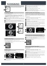
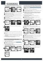
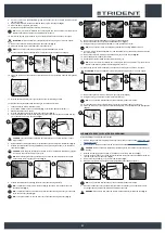
Seat adjustment
: The seat should always be positioned using the pedals as a reference. To adjust
the seat use the lever (1) under it (
Fig.1
).
N.B.:
The distance should be adjusted so that with the
pedals fully pressed to the floor the knees are slightly bent
(about 120°).
N.B.:
Adjust the distance of the seat so that when pressing
the brake pedal it goes as far as it can. This operation
should be done with the machine running so as to pressurise the
braking system.
N.B.:
If the knee is not bent enough, it is too far from the
steering wheel, if however the knee is bent almost 90°then it is
too close to the steering wheel.
N.B.:
The feet should be positioned keeping the heels on the footrest, the sole of the foot
directly below the fingers should push the pedals.
N.B.:
The ideal position is that which allows you to grip the steering wheel correctly with the
palms slightly lower than the shoulders. With a good grip on the steering wheel, the elbows
should be bent by about 120°. They should be at least 30 cm between the middle of the
steering wheel and our breastbone. In any case, this distance should be no more than 45 cm.
Adjusting the armrests (optional):
the armrests should be inclined to make using the machine
comfortable.
N.B.:
To adjust the armrest use the runner (2) under it (
Fig.2
).
N.B.:
Taking the right armrest as a reference, if the wheel is
turned outwards the inclination of the armrest is increased.
Taking the left armrest as a reference, if the wheel is turned inwards
the inclination of the armrest is increased.
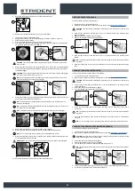
Wear the seatbelt correctly (optional):
The machine has a sub-abdominal safety device that allows
the operator to be anchored to the driver's seat. To secure the safety belt, first of all you need to be
sitting in the drier's seat, take the mobile part (3) of the belt, wrap it round the abdomen and insert the
mobile part (3) in the slit in the fixed part (4) (
Fig.3
).
1
1
1
2
N.B.:
Adjust the horizontal part of the belt so it is as tight
as possible on the pelvis. The belt should be pulled and
put as low as possible on the pelvis bone, and not on the belly.
1
3
4
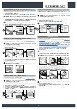
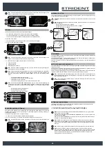
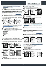
INSERTING WATER SYSTEM FILTER
Before using the machine for the first time the water system filter needs to be reset, for shipping reasons
the filter cartridge and the cap have been removed. To insert the filter cartridge in the water system
filter body proceed as follows:
1. Take the machine to the maintenance area.
2. Make sure the machine has been secured (see the section titled “
CAUTION
: users are advised to always wear protective gloves, to avoid the risk of serious injury
to hands.
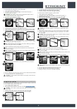
3.
Close the tap's output flow, and shift the knob (1) on the left hand side of the steering column
(
Fig.1
) downward.
4. Open the machine's left lateral hatch (2) (
Fig.2
).
5.
Insert the filter cartridge (3) in the housing on the cap (4) (
Fig.3
).
N.B.:
The O-ring gasket in the filter cartridge should be inserted into its seat in the cap.
6.
Screw on the cap (4) to the body of the detergent solution filter (5) (
Fig.4
).
N.B.:
For the sweeping versions, the water system filter is located on the right of the machine.
2
3
1
1
2
3
4
4
5
4
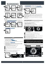
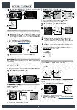
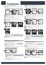
ASSEMBLING THE BRUSH HEAD BRUSHES (SCRUBBING VERSION)
To fit the brush on the brush head body, proceed as follows:
1. Take the machine to the maintenance area.
2. Make sure the machine has been secured (see the section titled “
SECURING THE MACHINE
”).
CAUTION
: these operations must be carried out using protective gloves to avoid any possible
contact with the edges or tips of metal objects.
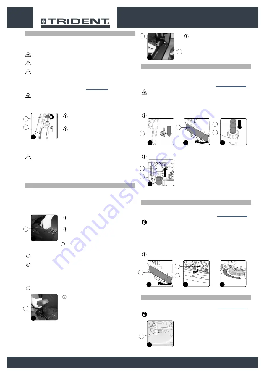
3. Open the machine's left lateral carter (1) (
Fig.1
).
4.
Remove the left-hand splashguard (2) and move the fixing anchors (3) on the brush head body into
the maintenance position (
Fig.2
).
5. With the brush head UP, insert the brush in the plate housing underneath the brush head, turning
it until the three buttons engage with the niches on the plate itself.
6. Turn in increments until the button is pushed towards the coupling spring and is locked in place
(
Fig.3
).
N.B.
: The image in
Fig.3
indicates the direction of rotation for coupling the left brush; the right
brush must be turned in the opposite direction.
3
1
2
1
2
3
FITTING LATERAL BRUSH 1SL (SCRUBBING )
To fit the side brush on the brush head body, proceed as follows:
1. Make sure the machine has been secured (see the section titled “
CAUTION
: these operations must be carried out using protective gloves to avoid any possible
contact with the edges or tips of metal objects.
2. With the brush head in its resting position, insert the brush into the
plate housing underneath the brush head, and turn it until the two
buttons engage with the niches on the plate itself (
Fig.1
).
3. Push the brush until the stopper spring on the brush itself has
engaged with the niche present on the gear motor’s pin
.
1
1
18


