


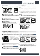


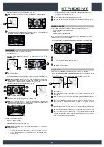
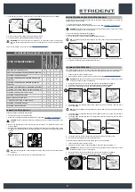
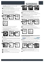
ASSEMBLING THE BRUSH HEAD BRUSHES (SWEEPING VERSION)
To fit the brush on the brush head body, proceed as follows:
1. Make sure the machine has been secured (see the section titled “
CAUTION
: these operations must be carried out using protective gloves to avoid any possible
contact with the edges or tips of metal objects.
2. Open the machine's left lateral carter (1) (
Fig.1
).
3. With the brush head in its resting position, turn the knobs (2) that hold the left lateral carter (3) in
place anti-clockwise (
Fig.2
).
4. Remove the left lateral carter (4) (
Fig.3
).
5. Insert the brush into the tunnel (
Fig.4
), taking care to make sure that the gear motor’s drive shaft
enters the slit in the brush itself.
6. Repeat the previously described operations for the right-hand side as well.
N.B.
: In order to be installed correctly, the brushes must form an X when viewed from above in
the forward direction of movement (
Fig.5
).
1
1
2
2
3
3
4
5
4
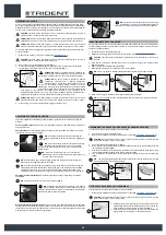
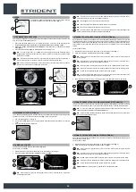
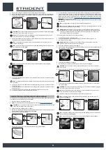
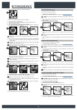
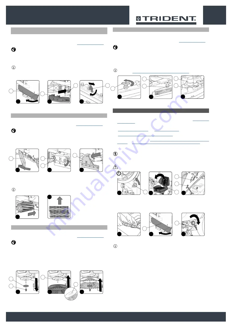
ASSEMBLING SIDE BRUSH 2SL (SWEEPING VERSION)
To fit the brush on the brush head body, proceed as follows:
1. Make sure the machine has been secured (see the section titled “
CAUTION
: these operations must be carried out using protective gloves to avoid any possible
contact with the edges or tips of metal objects.
2. Stand on the right side of the machine.
3. With the brush head in its raised position, remove the knob (1) that secures the side brush to the
gear motor, turning it clockwise for the right brush, and anti-clockwise for the left brush (
Fig.1
).
4. Remove the washer (2) holding the side brush in place (
Fig.1
).
5. Insert the side brush, being careful to position the centring hex (3) correctly in the slot (4) (
Fig.2
).
6.
Fix the brush to the flange using the knob (1), remembering to put the washer (2) in between the
knob and the brush (
Fig.3
).
7.
Once the brush has been fitted, move on to the one on the left.
1
3
2
2
1
3
4
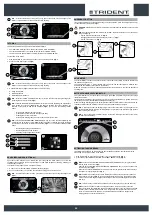
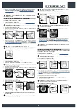
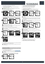
ASSEMBLING THE SQUEEGEE BODY
For packaging reasons, the squeegee body comes disassembled from the machine. In order to mount
it on the squeegee support, do the following:
1. Make sure the machine has been secured (see the section titled “
”).
CAUTION
: these operations must be carried out using protective gloves to avoid any possible
contact with the edges or tips of metal objects.
2. Unscrew the knobs (1) in the squeegee body pre-assembly (
Fig.1
).
3. First, insert the left pin (2) on the squeegee body into the left slit (3) in the squeegee support
(
Fig.2
), so that the bushing adheres to the walls of the slit in the squeegee support.
4. Repeat the same operation for the right pin.
5. Insert the vacuum tube (4) in the sleeve (5) in the squeegee body (
Fig.3
).
N.B.
: Although the squeegee comes pre-adjusted, it is nevertheless recommended to read the
ADJUSTING THE SQUEEGEE BODY'S RUBBER BLADES
1
2
3
5
4
1
3
2
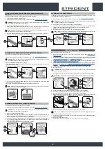
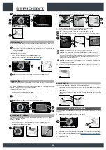
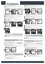
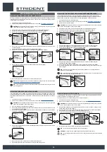
PREPARING TO WORK
Before beginning to work, it is necessary to:
1. Make sure the recovery tank is empty. If this is not the case, empty it (read “
”).
2.
Check that the amount of detergent solution present in the solution tank is sufficient for the type
of work to be performed. If this is not the case, top up the solution tank (see the sections titled
“
”).
3. Check that the squeegee rubbers are in good working condition. If not, carry out maintenance (see
“
REPLACING THE SQUEEGEE BODY RUBBER BLADES
4. Check that the condition of the brushes is suitable for the work to be carried out; if not, perform
the necessary maintenance (see “
ASSEMBLING THE BRUSH HEAD BRUSHES (SCRUBBING
ASSEMBLING THE BRUSH HEAD BRUSHES (SWEEPING VERSION)
5. Set the main machine switch to “0” (
Fig.1
). Remove the key from the instrument panel.
6.
Get off the machine.
CAUTION
: when getting down from the machine, do not place your foot on the scrubbing brush
head or side brush head brush.
7. Grip the back of the seat (2) and turn the seat support plate to its maintenance position (
Fig.2
).
ATTENTION:
to prevent the seat from rotating, insert the retainer (3) into the slot (4) (
Fig.3
).
8. Connect the battery connector from the main machine system connector (
Fig.4
).
9. Grip the back of the seat (2) and turn the seat support plate to the working position.
10. Move to the left side of the machine and open the left side casing (5) (
Fig.5
).
11. Make sure the electronic brake is engaged. If it isn't, turn the lever (6) in the direction of the arrow
(
Fig.6
). The traction gear motor is located on the rear right-hand side of the machine.
12.
Make sure the water system filter cap (7) is closed. If it isn't, close it (
Fig.7
).
N.B.:
For the sweeping versions, the water system filter is located on the right of the machine.
13. Close the left side casing of the machine.
14. Check that the water tap is fully open, move the water adjustment knob (8) in the direction shown
by the arrow (
Fig.8
).
15. Stand at the back of the machine.
16. Check that the solution tank drainage cap (9) is closed. If it is not, close it (
Fig.9
).
3
3
4
2
2
1
1
OFF
5
6
4
5
6
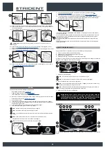
FITTING THE BRUSH HEAD BODY SIDE SPLASHGUARDS (WASHING
VERSION)
To fit the side splashguards on the brush head body, proceed as follows:
1. Take the machine to the maintenance area.
2. Make sure the machine has been secured (see the section titled “
SECURING THE MACHINE
”).
CAUTION
: These operations must be carried out using protective gloves to avoid any possible
contact with the edges or tips of metal objects.
3. Open the machine's left lateral carter (1) (
Fig.1
).
4.
With the brush head raised from the floor, position the side splashguard casing on the brush head
body, insert the pins (2) in the brush head in the slots (3) in the casing (
Fig.2
).
N.B.
: Before inserting the pins (2) in the slots (3) remember to put the fixing anchors (4) in the
brush head body in the maintenance position (
Fig.3
).
5.
When the side splashguard casing is in position turn the fixing anchors (4) to the work position.
6. Close the left side casing (1) and repeat everything for the right side casing.
3
1
2
1
2
4
3
19


